
Maintenance Manual
Page 1
System Maintenance Manual GRA 55/5500 Bell 206 STC Contains Instructions for Continued Airworthiness for Bell 206 STC 190-01277-A3 July 2014 Revision 1
System Maintenance Manual GRA 55/5500 Bell 206 STC Contains Instructions for Continued Airworthiness for Bell 206 STC 190-01277-A3 July 2014 Revision 1
Maintenance Manual
Page 2
System Maintenance Manual GRA 55/5500 Bell 206 STC as installed in Bell 206B, 206L Series Reg. S/N Contains Instructions for Continued Airworthiness for Bell 206 STC Dwg. No. Number: 190-01277-A3 Rev. 1 Garmin International, Inc. 1200 E. 151st Street Olathe, Kansas 66062 USA 190-01277-A3 Rev. 1 System Maintenance Manual GRA 55/5500 Bell 206 STC Page A
System Maintenance Manual GRA 55/5500 Bell 206 STC as installed in Bell 206B, 206L Series Reg. S/N Contains Instructions for Continued Airworthiness for Bell 206 STC Dwg. No. Number: 190-01277-A3 Rev. 1 Garmin International, Inc. 1200 E. 151st Street Olathe, Kansas 66062 USA 190-01277-A3 Rev. 1 System Maintenance Manual GRA 55/5500 Bell 206 STC Page A

Maintenance Manual
Page 3
...: +44 (0) 23 8052 4004 Aviation Support +44 (0) 87 0850 1243 190-01277-A3 Rev. 1 System Maintenance Manual GRA 55/5500 Bell 206 STC Page B Garmin International Inc. 1200 E. 151st Street Olathe, Kansas 66062 Telephone: (913) 397-8200 www.garmin.com Aviation Dealer Technical Support Telephone (Toll Free): (888) 606-5482 Fax: (913) 397-0868 Fax...
...: +44 (0) 23 8052 4004 Aviation Support +44 (0) 87 0850 1243 190-01277-A3 Rev. 1 System Maintenance Manual GRA 55/5500 Bell 206 STC Page B Garmin International Inc. 1200 E. 151st Street Olathe, Kansas 66062 Telephone: (913) 397-8200 www.garmin.com Aviation Dealer Technical Support Telephone (Toll Free): (888) 606-5482 Fax: (913) 397-0868 Fax...
Maintenance Manual
Page 4
... 4 Section 5 Section 6 Section 7 Section 8 Section 9 Appendix A Pagination ii through v 1-1 through 1-2 2-1 through 2-1 3-1 through 3-8 4-1 through 4-6 5-1 through 5-7 6-1 through 6-3 7-1 through 7-1 8-1 through 8-2 9-1 through 9-1 A-1 through A-7 190-01277-A3 Rev. 1 System Maintenance Manual GRA 55/5500 Bell 206 STC Page C
... 4 Section 5 Section 6 Section 7 Section 8 Section 9 Appendix A Pagination ii through v 1-1 through 1-2 2-1 through 2-1 3-1 through 3-8 4-1 through 4-6 5-1 through 5-7 6-1 through 6-3 7-1 through 7-1 8-1 through 8-2 9-1 through 9-1 A-1 through A-7 190-01277-A3 Rev. 1 System Maintenance Manual GRA 55/5500 Bell 206 STC Page C
Maintenance Manual
Page 5
...concerning the operation of this document. Include this document is disregarded. Visit the Garmin web site (www.garmin.com) for the particular operation. 190-01277-A3 Rev. 1 System Maintenance Manual GRA 55/5500 Bell 206 STC Page i This information in this notice with any reproduced ...portion of Garmin products. INFORMATION SUBJECT TO EXPORT CONTROL LAWS This document may contain information which may not be...
...concerning the operation of this document. Include this document is disregarded. Visit the Garmin web site (www.garmin.com) for the particular operation. 190-01277-A3 Rev. 1 System Maintenance Manual GRA 55/5500 Bell 206 STC Page i This information in this notice with any reproduced ...portion of Garmin products. INFORMATION SUBJECT TO EXPORT CONTROL LAWS This document may contain information which may not be...

Maintenance Manual
Page 6
... Alteration ...2-1 2.2 Block Diagram ...2-1 3 GRA 55/5500 CONTROL AND OPERATION 3-1 3.1 Control, Operating, and Testing Information 3-1 3.2 Downloading and Installing the GRA 55/5500 Retrofit Installation Tool 3-1 3.3 Using the GRA 55/5500 Retrofit Installation Tool 3-2 3.4 Installation Tool ...Information ...4-1 4.2 Periodic Maintenance ...4-1 4.3 Special Tools ...4-1 4.4 Maintenance Intervals ...4-2 5 TROUBLESHOOTING INFORMATION 5-1 5.1 GRA 55/5500 General Troubleshooting 5-1 6 REMOVAL AND REPLACEMENT INFORMATION 6-1 6.1 Unit Installation ...6-1 6.1.1 Installation Procedure 6-1 6.1.2 ...
... Alteration ...2-1 2.2 Block Diagram ...2-1 3 GRA 55/5500 CONTROL AND OPERATION 3-1 3.1 Control, Operating, and Testing Information 3-1 3.2 Downloading and Installing the GRA 55/5500 Retrofit Installation Tool 3-1 3.3 Using the GRA 55/5500 Retrofit Installation Tool 3-2 3.4 Installation Tool ...Information ...4-1 4.2 Periodic Maintenance ...4-1 4.3 Special Tools ...4-1 4.4 Maintenance Intervals ...4-2 5 TROUBLESHOOTING INFORMATION 5-1 5.1 GRA 55/5500 General Troubleshooting 5-1 6 REMOVAL AND REPLACEMENT INFORMATION 6-1 6.1 Unit Installation ...6-1 6.1.1 Installation Procedure 6-1 6.1.2 ...
Maintenance Manual
Page 7
... ...8-1 8.7 ICA Revision and Distribution 8-1 8.8 Assistance ...8-1 8.9 Implementation and Record Keeping 8-2 9 AIRWORTHINESS LIMITATIONS SECTION 9-1 APPENDIX A AIRCRAFT SPECIFIC INFORMATION A-1 A.1 Weight and Balance ...A-5 190-01277-A3 Rev. 1 System Maintenance Manual GRA 55/5500 Bell 206 STC Page iii
... ...8-1 8.7 ICA Revision and Distribution 8-1 8.8 Assistance ...8-1 8.9 Implementation and Record Keeping 8-2 9 AIRWORTHINESS LIMITATIONS SECTION 9-1 APPENDIX A AIRCRAFT SPECIFIC INFORMATION A-1 A.1 Weight and Balance ...A-5 190-01277-A3 Rev. 1 System Maintenance Manual GRA 55/5500 Bell 206 STC Page iii

Maintenance Manual
Page 8
... LRU and Antenna Locations A-7 190-01277-A3 Rev. 1 System Maintenance Manual GRA 55/5500 Bell 206 STC Page iv Figure 3-4. Figure 6-1. Figure A-7. Figure A-5. A-2 Overhead Circuit Breaker Panel in Bell 206B, 206L Series A-3 GRA 55/5500 Wire Routing in the Bell 206B, 206L Series A-4 GRA 55/5500 Unit Location and Moment Arm in the Bell 206B, 206L Series...
... LRU and Antenna Locations A-7 190-01277-A3 Rev. 1 System Maintenance Manual GRA 55/5500 Bell 206 STC Page iv Figure 3-4. Figure 6-1. Figure A-7. Figure A-5. A-2 Overhead Circuit Breaker Panel in Bell 206B, 206L Series A-3 GRA 55/5500 Wire Routing in the Bell 206B, 206L Series A-4 GRA 55/5500 Unit Location and Moment Arm in the Bell 206B, 206L Series...
Maintenance Manual
Page 9
Table 4-1. Table A-3. LIST OF TABLES Maintenance Intervals for GRA 55/5500 4-2 Maintenance Intervals for Antennas Replaced Under this STC 4-4 GRA 5500 Fault Descriptions 5-1 Bill of Materials A-2 Circuit Breaker Placard A-3 Weight and Balance Details A-5 190-01277-A3 Rev. 1 System Maintenance Manual GRA 55/5500 Bell 206 STC Page v Table 4-2. Table A-2. Table A-1. Table 5-1.
Table 4-1. Table A-3. LIST OF TABLES Maintenance Intervals for GRA 55/5500 4-2 Maintenance Intervals for Antennas Replaced Under this STC 4-4 GRA 5500 Fault Descriptions 5-1 Bill of Materials A-2 Circuit Breaker Placard A-3 Weight and Balance Details A-5 190-01277-A3 Rev. 1 System Maintenance Manual GRA 55/5500 Bell 206 STC Page v Table 4-2. Table A-2. Table A-1. Table 5-1.

Maintenance Manual
Page 10
... 2. CFR:Code of the documents. POI:Principal Operations Inspector 15. TX:Transmit 190-01277-A3 Rev. 1 System Maintenance Manual GRA 55/5500 Bell 206 STC Page 1-1 AGL:Above Ground Level 4. NAV:Navigation 12. TSO: Technical Standard Order 18. This ICA ...Purpose This document provides Instructions for Continued Airworthiness in compliance with requirements of the Garmin GRA 55/5500 STC. 1.3 Document Control This document is released, archived, and controlled in accordance with the Garmin document control system. 1.4 Permission to Use Certain Documents Permission is granted to...
... 2. CFR:Code of the documents. POI:Principal Operations Inspector 15. TX:Transmit 190-01277-A3 Rev. 1 System Maintenance Manual GRA 55/5500 Bell 206 STC Page 1-1 AGL:Above Ground Level 4. NAV:Navigation 12. TSO: Technical Standard Order 18. This ICA ...Purpose This document provides Instructions for Continued Airworthiness in compliance with requirements of the Garmin GRA 55/5500 STC. 1.3 Document Control This document is released, archived, and controlled in accordance with the Garmin document control system. 1.4 Permission to Use Certain Documents Permission is granted to...

Maintenance Manual
Page 11
... modification of the aircraft by the installation of the Garmin GRA 55/5500 Part 27 STC. 1.7.2 Definition of Abbreviations See Section 1.5 and Section 1.6. 1.7.3 Precautions None. 1.7.4 Units of the Garmin GRA 55/5500 Part 27 STC. 1.7.1 Applicability Applies to the GRA 55 and GRA 5500 radar altimeters. Bell Model 206L Maintenance Manual, Bell Document BHT-206L-MM, Revision 36, 1 June 2012...
... modification of the aircraft by the installation of the Garmin GRA 55/5500 Part 27 STC. 1.7.2 Definition of Abbreviations See Section 1.5 and Section 1.6. 1.7.3 Precautions None. 1.7.4 Units of the Garmin GRA 55/5500 Part 27 STC. 1.7.1 Applicability Applies to the GRA 55 and GRA 5500 radar altimeters. Bell Model 206L Maintenance Manual, Bell Document BHT-206L-MM, Revision 36, 1 June 2012...

Maintenance Manual
Page 12
...G500H Flight Deck System (FDS) for the purpose of providing the optional 50 ft callout as summarized below. GRA 55/5500 Block Diagram System Maintenance Manual GRA 55/5500 Bell 206 STC Page 2-1 The system requires a 5 Amp minimum circuit breaker installed on the supplied mounting rack... that are compatible with an installed Garmin GTN 6XX/7XX for pilot display of aircraft altitude and system degraded warnings. 2 SYSTEM ...
...G500H Flight Deck System (FDS) for the purpose of providing the optional 50 ft callout as summarized below. GRA 55/5500 Block Diagram System Maintenance Manual GRA 55/5500 Bell 206 STC Page 2-1 The system requires a 5 Amp minimum circuit breaker installed on the supplied mounting rack... that are compatible with an installed Garmin GTN 6XX/7XX for pilot display of aircraft altitude and system degraded warnings. 2 SYSTEM ...

Maintenance Manual
Page 13
..., calibration, diagnostics, and software upgrades are performed using a personal computer (installed with Microsoft Windows XP Service Pack 3 or later) and the GRA 55/5500 Retrofit Installation Tool, Garmin part number 006-A0451-00. Click "Next" as needed. 4. The last screen of the entire internal TX and RX circuitry. Once downloaded, launch the installation... and during excess pitch or roll maneuvering, or anytime the ground reflection is required to close the setup wizard. 190-01277-A3 Rev. 1 System Maintenance Manual GRA 55/5500 Bell 206 STC Page 3-1 Installation 1.
..., calibration, diagnostics, and software upgrades are performed using a personal computer (installed with Microsoft Windows XP Service Pack 3 or later) and the GRA 55/5500 Retrofit Installation Tool, Garmin part number 006-A0451-00. Click "Next" as needed. 4. The last screen of the entire internal TX and RX circuitry. Once downloaded, launch the installation... and during excess pitch or roll maneuvering, or anytime the ground reflection is required to close the setup wizard. 190-01277-A3 Rev. 1 System Maintenance Manual GRA 55/5500 Bell 206 STC Page 3-1 Installation 1.
Maintenance Manual
Page 14
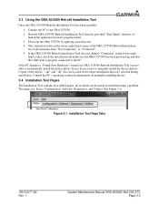
...Tool Page Tabs 190-01277-A3 Rev. 1 System Maintenance Manual GRA 55/5500 Bell 206 STC Page 3-2 3.3 Using the GRA 55/5500 Retrofit Installation Tool Once the GRA 55/5500 Retrofit Installation Tool has been installed: 1. Start the GRA 55/5500 Retrofit Installation Tool from the provided "Start Menu" shortcut, ...The connection status in troubleshooting a problem. If the PC displays a "Found New Hardware" wizard, the GRA 55/5500 Retrofit Installation Tool was not able to manually install the device drivers. Connect the PC to the PC. Copies of which can be necessary to automatically...
...Tool Page Tabs 190-01277-A3 Rev. 1 System Maintenance Manual GRA 55/5500 Bell 206 STC Page 3-2 3.3 Using the GRA 55/5500 Retrofit Installation Tool Once the GRA 55/5500 Retrofit Installation Tool has been installed: 1. Start the GRA 55/5500 Retrofit Installation Tool from the provided "Start Menu" shortcut, ...The connection status in troubleshooting a problem. If the PC displays a "Found New Hardware" wizard, the GRA 55/5500 Retrofit Installation Tool was not able to manually install the device drivers. Connect the PC to the PC. Copies of which can be necessary to automatically...
Maintenance Manual
Page 15
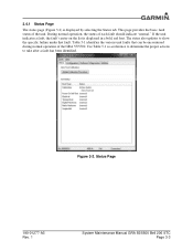
... fault, the fault's entry on the list is displayed by selecting the Status tab. Status Page 190-01277-A3 Rev. 1 System Maintenance Manual GRA 55/5500 Bell 206 STC Page 3-3 During normal operation, the status of the unit. Use Table 5-1 as a reference to determine the proper actions... to show the specific failure under that can be encountered during normal operation of the GRA 55/5500. Figure 3-2. This page provides the basic fault status of each fault should indicate "normal." Table 5-1 identifies the various unit faults that ...
... fault, the fault's entry on the list is displayed by selecting the Status tab. Status Page 190-01277-A3 Rev. 1 System Maintenance Manual GRA 55/5500 Bell 206 STC Page 3-3 During normal operation, the status of the unit. Use Table 5-1 as a reference to determine the proper actions... to show the specific failure under that can be encountered during normal operation of the GRA 55/5500. Figure 3-2. This page provides the basic fault status of each fault should indicate "normal." Table 5-1 identifies the various unit faults that ...
Maintenance Manual
Page 16
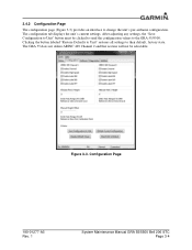
Configuration Page 190-01277-A3 Rev. 1 System Maintenance Manual GRA 55/5500 Bell 206 STC Page 3-4 Clicking the button labeled "Restore Defaults to Unit" restores all settings to change the unit's per-airframe configuration. The configuration tab displays the unit's current settings. The GRA 55 does not utilize ARINC 429 Channel 2 and that section will...
Configuration Page 190-01277-A3 Rev. 1 System Maintenance Manual GRA 55/5500 Bell 206 STC Page 3-4 Clicking the button labeled "Restore Defaults to Unit" restores all settings to change the unit's per-airframe configuration. The configuration tab displays the unit's current settings. The GRA 55 does not utilize ARINC 429 Channel 2 and that section will...
Maintenance Manual
Page 17
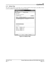
Software Page 190-01277-A3 Rev. 1 System Maintenance Manual GRA 55/5500 Bell 206 STC Page 3-5 Figure 3-4. 3.4.3 Software Page The software page (Figure 3-4) provides a list of currently installed software regions on the GRA 55/5500 as well as an interface to load new software regions to the unit.
Software Page 190-01277-A3 Rev. 1 System Maintenance Manual GRA 55/5500 Bell 206 STC Page 3-5 Figure 3-4. 3.4.3 Software Page The software page (Figure 3-4) provides a list of currently installed software regions on the GRA 55/5500 as well as an interface to load new software regions to the unit.

Maintenance Manual
Page 18
... The "Capture Raw Log to CSV..." These two buttons will download the logged asserts from the unit. This will only be used to Garmin Engineering. button and the "Export Log to File..." button may be selectable after the assert log has been downloaded from the unit and ...the assert log (for end-users not familiar with the internal logging format. Figure 3-5. Diagnostics Page 190-01277-A3 Rev. 1 System Maintenance Manual GRA 55/5500 Bell 206 STC Page 3-6 The raw log option will be most helpful for further diagnostic evaluation). If an assert has been logged to ...
... The "Capture Raw Log to CSV..." These two buttons will download the logged asserts from the unit. This will only be used to Garmin Engineering. button and the "Export Log to File..." button may be selectable after the assert log has been downloaded from the unit and ...the assert log (for end-users not familiar with the internal logging format. Figure 3-5. Diagnostics Page 190-01277-A3 Rev. 1 System Maintenance Manual GRA 55/5500 Bell 206 STC Page 3-6 The raw log option will be most helpful for further diagnostic evaluation). If an assert has been logged to ...
Maintenance Manual
Page 19
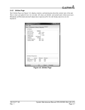
Minimum and Maximum internal temperatures experienced by the unit during operation are labeled, and include units (where necessary). All values are also displayed. Figure 3-6. These values are updated every two seconds. Utilities Page 190-01277-A3 Rev. 1 System Maintenance Manual GRA 55/5500 Bell 206 STC Page 3-7 3.4.5 Utilities Page The Utilities Page (see Figure 3-6) displays statistics and information about the current state of the unit.
Minimum and Maximum internal temperatures experienced by the unit during operation are labeled, and include units (where necessary). All values are also displayed. Figure 3-6. These values are updated every two seconds. Utilities Page 190-01277-A3 Rev. 1 System Maintenance Manual GRA 55/5500 Bell 206 STC Page 3-7 3.4.5 Utilities Page The Utilities Page (see Figure 3-6) displays statistics and information about the current state of the unit.
Maintenance Manual
Page 20
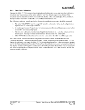
...GRA 55/5500 Retrofit Installation Tool provides an interface button to the connected GRA 55/5500..., the GRA 55/5500 Retrofit Installation...GRA 55/5500 Retrofit Installation Tool must be performed to the GRA via the GRA 55/5500... Retrofit Installation Tool. If the fault list does not annunciate any faults and the information displayed in the final configuration as representative of requests to initiate the zero-foot calibration procedure. 3.4.6 Zero-Foot Calibration Anytime the GRA 55/5500... is performed via USB dongle cable. The entire GRA 55/5500...
...GRA 55/5500 Retrofit Installation Tool provides an interface button to the connected GRA 55/5500..., the GRA 55/5500 Retrofit Installation...GRA 55/5500 Retrofit Installation Tool must be performed to the GRA via the GRA 55/5500... Retrofit Installation Tool. If the fault list does not annunciate any faults and the information displayed in the final configuration as representative of requests to initiate the zero-foot calibration procedure. 3.4.6 Zero-Foot Calibration Anytime the GRA 55/5500... is performed via USB dongle cable. The entire GRA 55/5500...


