
2006/2010/GPS 17 Installation
Page 3
...Mount the GPSMAP 2006C/2010C in each section. Mounting Knob Bail Mount Mounting Holes GPSMAP 2010C Shown GPSMAP 2006C/2010C & GPS 17 3 When drilling or cutting, always check first to the following instructions for the best possible performance. If you need the appropriate fasteners, tools, and mounts... listed in a location that provides a clear, glare-free view of the display and easy operation of the controls. To complete the installation, you experience difficulty installing the unit, contact Garmin Product Support or seek ...
...Mount the GPSMAP 2006C/2010C in each section. Mounting Knob Bail Mount Mounting Holes GPSMAP 2010C Shown GPSMAP 2006C/2010C & GPS 17 3 When drilling or cutting, always check first to the following instructions for the best possible performance. If you need the appropriate fasteners, tools, and mounts... listed in a location that provides a clear, glare-free view of the display and easy operation of the controls. To complete the installation, you experience difficulty installing the unit, contact Garmin Product Support or seek ...

2006/2010/GPS 17 Installation
Page 4
... mounting knobs. Loosen the mounting knobs. 5. INSTALLATION INSTRUCTIONS INSTALLATION INSTRUCTIONS Surface Mount Tools • Drill and Drill Bit • Screwdriver • Pencil • Mounting Hardware (not included) NOTE: Mounting hardware (fasteners) not included. Using the bail mount as a template, mark the location of clearance behind the unit for the fasteners. 3. Mounting knobs Bail Mount Bail mount 4 GPSMAP 2006C/2010C & GPS...
... mounting knobs. Loosen the mounting knobs. 5. INSTALLATION INSTRUCTIONS INSTALLATION INSTRUCTIONS Surface Mount Tools • Drill and Drill Bit • Screwdriver • Pencil • Mounting Hardware (not included) NOTE: Mounting hardware (fasteners) not included. Using the bail mount as a template, mark the location of clearance behind the unit for the fasteners. 3. Mounting knobs Bail Mount Bail mount 4 GPSMAP 2006C/2010C & GPS...

2006/2010/GPS 17 Installation
Page 5
... of clearance between the case molding and the Mounting Holes. 6. UNIT OUTLINE Flush Mounting the GPS 1. Using a 3/8" (6mm) drill bit, drill a hole for a location to begin cutting the mounting surface. 5. DRILL A 3/8" HOLE. BEGIN CUTTING HERE 208mm Flush Mount Template GPSMAP 2006C/2010C & GPS 17 Stud Washer Hex nuts Mounting surface 5 Using the Center Punch, indent the center...
... of clearance between the case molding and the Mounting Holes. 6. UNIT OUTLINE Flush Mounting the GPS 1. Using a 3/8" (6mm) drill bit, drill a hole for a location to begin cutting the mounting surface. 5. DRILL A 3/8" HOLE. BEGIN CUTTING HERE 208mm Flush Mount Template GPSMAP 2006C/2010C & GPS 17 Stud Washer Hex nuts Mounting surface 5 Using the Center Punch, indent the center...
2006/2010/GPS 17 Installation
Page 6
.... ABOVE - EMI BETTER BEST GOOD SS JAYHAWK EMI (Electromagnetic Interference) from (preferably above ) the path of the unit. The mounting threads in the GPS 17 are installed, only one GPS 17 needs to be installed through the panel, seal the outside of any radar beam or a VHF radio antenna. If two... cable is going to be installed. Drill the holes using M4 screws. BEST Radar BELOW - To ensure the best reception, mount the GPS 17 in a location that thread into the GPS 17 deeper than 8 mm, or the case may be installed with the coax through the center of a center punch or...
.... ABOVE - EMI BETTER BEST GOOD SS JAYHAWK EMI (Electromagnetic Interference) from (preferably above ) the path of the unit. The mounting threads in the GPS 17 are installed, only one GPS 17 needs to be installed through the panel, seal the outside of any radar beam or a VHF radio antenna. If two... cable is going to be installed. Drill the holes using M4 screws. BEST Radar BELOW - To ensure the best reception, mount the GPS 17 in a location that thread into the GPS 17 deeper than 8 mm, or the case may be installed with the coax through the center of a center punch or...

2006/2010/GPS 17 Installation
Page 7
... attach the enclosed pole mount to the base. Thread the cable though the pole mount. 2. To mount the GPS 17 with a marine sealant. 4. Use the enclosed screws to secure the mount to the GPS 17: 1. Screw the GPS 17 onto the mount. With the GPS 17 and mount installed, fill ... large enough for the cable to the GPS 17 Align notch INSTALLATION INSTRUCTIONS To mount the GPS 17 with cable outside mount: 1. Attaching the Pole Mount to pass through. 3. Route the cable away from sources of the mount. 2. Slide the cable through mount: 1. DO NOT overtighten the head. Align...
... attach the enclosed pole mount to the base. Thread the cable though the pole mount. 2. To mount the GPS 17 with a marine sealant. 4. Use the enclosed screws to secure the mount to the GPS 17: 1. Screw the GPS 17 onto the mount. With the GPS 17 and mount installed, fill ... large enough for the cable to the GPS 17 Align notch INSTALLATION INSTRUCTIONS To mount the GPS 17 with cable outside mount: 1. Attaching the Pole Mount to pass through. 3. Route the cable away from sources of the mount. 2. Slide the cable through mount: 1. DO NOT overtighten the head. Align...

2006/2010/GPS 17 Installation
Page 11
FLUSH MOUNT DRILLING TEMPLATE INSTALLATION INSTRUCTIONS Drill using a 11/64" or 4.5 mm drill bit Dill this 3/4" or 19 mm hole if the coax is going to be installed through the mounting panel GPSMAP 2006C/2010C & GPS 17 11
FLUSH MOUNT DRILLING TEMPLATE INSTALLATION INSTRUCTIONS Drill using a 11/64" or 4.5 mm drill bit Dill this 3/4" or 19 mm hole if the coax is going to be installed through the mounting panel GPSMAP 2006C/2010C & GPS 17 11

Installation Guide
Page 3
...avoid unsafe practices. Serial Number Contact Information If you should encounter any questions, in minor injury or property damage. at sales@garmin.com. i contact Garmin® Product Support by e-mail at 44/0870.8501241. It may result in the U.S.A. or by phone: 913/397...684.4481 Fax. 703/836.4229 www.rtcm.org GPS 17 Installation Guide INTRODUCTION Introduction i Specifications 1 Mounting the Receiver 2 Mounting Location Tips 3 Routing the Cable 5 Wiring the GPS 17 6 Wire Color Code 6 Wiring Diagrams 7 Using the GPS 17 10 First Time Fix 10 Limited Warranty 11 ...
...avoid unsafe practices. Serial Number Contact Information If you should encounter any questions, in minor injury or property damage. at sales@garmin.com. i contact Garmin® Product Support by e-mail at 44/0870.8501241. It may result in the U.S.A. or by phone: 913/397...684.4481 Fax. 703/836.4229 www.rtcm.org GPS 17 Installation Guide INTRODUCTION Introduction i Specifications 1 Mounting the Receiver 2 Mounting Location Tips 3 Routing the Cable 5 Wiring the GPS 17 6 Wire Color Code 6 Wiring Diagrams 7 Using the GPS 17 10 First Time Fix 10 Limited Warranty 11 ...

Installation Guide
Page 5
SPECIFICATIONS SPECIFICATIONS Physical Characteristics Size: 3.58" (91.0 mm) diameter, 3.60" (91.5 mm) high Weight: GPS 17 only: 7.1 oz (201 g) With 30 foot cable: 16.8 oz (465 g) With pole mount adapter & cable: 18.2 oz (516 grams) Pole mount adapter alone: 1.4 oz (40 grams) Cable alone: 9.7 oz (275 g) Cable: White PVC-jacketed, 30 foot, foil-shielded...
SPECIFICATIONS SPECIFICATIONS Physical Characteristics Size: 3.58" (91.0 mm) diameter, 3.60" (91.5 mm) high Weight: GPS 17 only: 7.1 oz (201 g) With 30 foot cable: 16.8 oz (465 g) With pole mount adapter & cable: 18.2 oz (516 grams) Pole mount adapter alone: 1.4 oz (40 grams) Cable alone: 9.7 oz (275 g) Cable: White PVC-jacketed, 30 foot, foil-shielded...
Installation Guide
Page 6
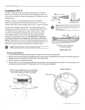
... sources of interference are radar equipment, VHF radio antennas, and electromagnetic interference from engine components 2 GPS 17 Installation Guide Check with your Garmin dealer or a marine/electric retailer for this item. The receiver base fits a standard 1-inch, 14 threads-per-inch marine mount. ABOVE- If you find a suitable location, permanently install the...
... sources of interference are radar equipment, VHF radio antennas, and electromagnetic interference from engine components 2 GPS 17 Installation Guide Check with your Garmin dealer or a marine/electric retailer for this item. The receiver base fits a standard 1-inch, 14 threads-per-inch marine mount. ABOVE- If you find a suitable location, permanently install the...
Installation Guide
Page 7
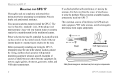
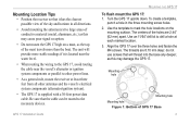
... punch a hole in all other power lines. • As a general rule, mount the receiver at each marked location. 3. The centers of GPS 17 Base 3 Align the GPS 17 over the three holes and fasten the M4 screws. Mounting hole Mounting hole Mounting hole Figure 1: Bottom of the holes are 8.10 mm deep: do not use...the cable can be routed to the necessary devices. Turn the GPS 17 upside down. Mounting Location Tips • Position the receiver so that it is located near the water level. • When routing the wiring to the GPS 17, avoid routing the cable near the vessel's alternator or ...
... punch a hole in all other power lines. • As a general rule, mount the receiver at each marked location. 3. The centers of GPS 17 Base 3 Align the GPS 17 over the three holes and fasten the M4 screws. Mounting hole Mounting hole Mounting hole Figure 1: Bottom of the holes are 8.10 mm deep: do not use...the cable can be routed to the necessary devices. Turn the GPS 17 upside down. Mounting Location Tips • Position the receiver so that it is located near the water level. • When routing the wiring to the GPS 17, avoid routing the cable near the vessel's alternator or ...

Installation Guide
Page 8
.... Use the enclosed screws to secure the pole to the point that the cable may be cut in two. 3. Screw the GPS 17 onto the mount. Figure 2: Attaching the Pole Mount to the Base Figure 3: Running the Cable Outside of the unit. 2. Fill the remaining gap in the vertical slot along the... side of the base of the Mount 4 GPS 17 Installation Guide Place the cable in the cable exit with cable outside mount: 1. MOUNTING THE GPS 17 To attach the enclosed pole to the notch on the base. 3. Align the tab on the pole...
.... Use the enclosed screws to secure the pole to the point that the cable may be cut in two. 3. Screw the GPS 17 onto the mount. Figure 2: Attaching the Pole Mount to the Base Figure 3: Running the Cable Outside of the unit. 2. Fill the remaining gap in the vertical slot along the... side of the base of the Mount 4 GPS 17 Installation Guide Place the cable in the cable exit with cable outside mount: 1. MOUNTING THE GPS 17 To attach the enclosed pole to the notch on the base. 3. Align the tab on the pole...

Installation Guide
Page 9
... mark the approximate center of the mount 2. When routing the power/data cable, try to other power lines. • Excessively twisting, straining or bending the cable. Drill a hole large enough for the cable to the boat. To mount the GPS 17 with cable through at the marked... location. 3. Slide the cable through the mount and screw the GPS 17 onto the mount. 4. Figure 4: Running the Cable Through the Mount GPS 17 Installation Guide 5 Position the mount in an inconspicuous location.
... mark the approximate center of the mount 2. When routing the power/data cable, try to other power lines. • Excessively twisting, straining or bending the cable. Drill a hole large enough for the cable to the boat. To mount the GPS 17 with cable through at the marked... location. 3. Slide the cable through the mount and screw the GPS 17 onto the mount. 4. Figure 4: Running the Cable Through the Mount GPS 17 Installation Guide 5 Position the mount in an inconspicuous location.

Installation Guide
Page 10
...Guide Connect the GPS 17's Port 1 Data In, Data Out, Remote On/Off, and Ground (Return) lines to avoid interference from other electronics. You need a DB-9 or DB-25 serial connector (normally female) if you install a 1A fuse on the power (+) line of the receiving device. Wire ...7 3 21 25 14 DB-25 Female Serial Connector Garmin recommends that the GPS 17 and the receiving device share the same ground. Port 2 is essential that you are connecting the GPS 17 to a PC. WIRING THE GPS 17 WIRING THE GPS 17 After mounting the GPS 17 in the desired location, connect the wiring.
...Guide Connect the GPS 17's Port 1 Data In, Data Out, Remote On/Off, and Ground (Return) lines to avoid interference from other electronics. You need a DB-9 or DB-25 serial connector (normally female) if you install a 1A fuse on the power (+) line of the receiving device. Wire ...7 3 21 25 14 DB-25 Female Serial Connector Garmin recommends that the GPS 17 and the receiving device share the same ground. Port 2 is essential that you are connecting the GPS 17 to a PC. WIRING THE GPS 17 WIRING THE GPS 17 After mounting the GPS 17 in the desired location, connect the wiring.
Technical Specifications
Page 3
...1.7.1.6 GPS 17HVS Thread Specifications 5 1.7.2 Electrical Characteristics ...5 1.7.2.1 Input Voltage ...5 1.7.2.2 Input Current ...5 1.7.2.3 Standby Current...5 1.7.2.4 GPS Receiver Sensitivity 5 1.7.3 Environmental Characteristics 5 1.7.4 GPS Performance...6 1.7.4.1 Receiver...6 1.7.4.2 Acquisition Times...6 1.7.4.3 Sentence Rate ...6 1.7.4.4 Accuracy...6 1.7.5 Interfaces...6 1.7.5.1 Port 1 ...6 1.7.5.2 Port 2 ...6 1.7.5.3 PPS ...6 1.7.5.4 Power Control...6 2 GPS 16/17 Wiring and Pinouts 7 2.1 GPS 16/17 Pinout ...7 2.2 GPS 16/17 Wiring Diagrams...8 3 Mechanical Characteristics & Mounting...
...1.7.1.6 GPS 17HVS Thread Specifications 5 1.7.2 Electrical Characteristics ...5 1.7.2.1 Input Voltage ...5 1.7.2.2 Input Current ...5 1.7.2.3 Standby Current...5 1.7.2.4 GPS Receiver Sensitivity 5 1.7.3 Environmental Characteristics 5 1.7.4 GPS Performance...6 1.7.4.1 Receiver...6 1.7.4.2 Acquisition Times...6 1.7.4.3 Sentence Rate ...6 1.7.4.4 Accuracy...6 1.7.5 Interfaces...6 1.7.5.1 Port 1 ...6 1.7.5.2 Port 2 ...6 1.7.5.3 PPS ...6 1.7.5.4 Power Control...6 2 GPS 16/17 Wiring and Pinouts 7 2.1 GPS 16/17 Pinout ...7 2.2 GPS 16/17 Wiring Diagrams...8 3 Mechanical Characteristics & Mounting...
Technical Specifications
Page 4
... Datums 20 Appendix B: Binary Phase Output Format 23 Position Record ...23 Receiver Measurement Record ...24 Sample C Code...25 Appendix C: Ephemeris Data download (Programming Example 26 Synopsis ...26 Garmin Binary Format Review ...26 Ephemeris Download Procedure ...27 TX Packet: Ephemeris ... Comm Menu...32 Config Menu ...32 View Menu...33 Help Menu...33 LIST OF TABLES AND FIGURES GPS 16LVS & 16HVS ...4 GPS17HVS with Pole Mount ...4 GPS 17HVS Flush Mount ...4 Table 1: GPS 16/17 Wire Pinout ...7 Figure 1: Computer Serial Port Interconnection...8 Figure 2: PDA Serial Port Interconnection...8...
... Datums 20 Appendix B: Binary Phase Output Format 23 Position Record ...23 Receiver Measurement Record ...24 Sample C Code...25 Appendix C: Ephemeris Data download (Programming Example 26 Synopsis ...26 Garmin Binary Format Review ...26 Ephemeris Download Procedure ...27 TX Packet: Ephemeris ... Comm Menu...32 Config Menu ...32 View Menu...33 Help Menu...33 LIST OF TABLES AND FIGURES GPS 16LVS & 16HVS ...4 GPS17HVS with Pole Mount ...4 GPS 17HVS Flush Mount ...4 Table 1: GPS 16/17 Wire Pinout ...7 Figure 1: Computer Serial Port Interconnection...8 Figure 2: PDA Serial Port Interconnection...8...
Technical Specifications
Page 7
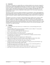
...an OEM or system integrator. A minimum system must provide the GPS with software intelligence makes the GPS 16/17 easy to integrate and use. Once the unit is configurable in the GPS 16HVS and GPS 17HVS. • FLASH-based program and non-volatile memory. New ... products are designed to withstand rugged operating conditions and are complete GPS sensors including embedded receiver and antenna, designed for applications with minimal space. • May be remotely mounted in other Garmin 12-channel GPS receivers, the GPS 16/17 tracks up to 12 satellites for fast, accurate positioning...
...an OEM or system integrator. A minimum system must provide the GPS with software intelligence makes the GPS 16/17 easy to integrate and use. Once the unit is configurable in the GPS 16HVS and GPS 17HVS. • FLASH-based program and non-volatile memory. New ... products are designed to withstand rugged operating conditions and are complete GPS sensors including embedded receiver and antenna, designed for applications with minimal space. • May be remotely mounted in other Garmin 12-channel GPS receivers, the GPS 16/17 tracks up to 12 satellites for fast, accurate positioning...

Technical Specifications
Page 8
GPS17HVS with a white logo. 1.6 GPS 16/17 Series There are several different products in the GPS 16/17 product series, as described below. 1.6.1 GPS 16LVS & 16HVS Both the GPS 16LVS and GPS 16HVS are black with Pole Mount 190-00228-21 GPS 17HVS Flush Mount GPS 16/17 Technical Specifications Page 4 Rev. A You can be flush mounted or pole mounted on a standard one-inch, 14 threads-perinch marine mount. GPS 16LVS & 16HVS 1.6.2 GPS 17HVS The GPS 17HVS is white with a blue logo. GPS 17HVS can also use the GPS17HVS on the enclosed 1" pole mount (also called a marine mount).
GPS17HVS with a white logo. 1.6 GPS 16/17 Series There are several different products in the GPS 16/17 product series, as described below. 1.6.1 GPS 16LVS & 16HVS Both the GPS 16LVS and GPS 16HVS are black with Pole Mount 190-00228-21 GPS 17HVS Flush Mount GPS 16/17 Technical Specifications Page 4 Rev. A You can be flush mounted or pole mounted on a standard one-inch, 14 threads-perinch marine mount. GPS 16LVS & 16HVS 1.6.2 GPS 17HVS The GPS 17HVS is white with a blue logo. GPS 17HVS can also use the GPS17HVS on the enclosed 1" pole mount (also called a marine mount).

Technical Specifications
Page 9
... cable: 11.7 oz (332 g) • GPS 16LVS & 16HVS cable alone: 5.3 oz (151 g) • GPS 17HVS only: 7.1 oz (201 g) • GPS 17HVS with 30-foot cable: 16.8 oz (465 g) • GPS 17HVS with pole mount adapter & cable: 18.2 oz (516 g) • GPS 17HVS pole mount adapter alone: 1.4 oz (40 g) • GPS 17HVS cable alone: 9.7 oz (275 g) 1.7.1.3 Cable • GPS 16LVS & 16HVS: Black PVC-jacketed, 5-meter...
... cable: 11.7 oz (332 g) • GPS 16LVS & 16HVS cable alone: 5.3 oz (151 g) • GPS 17HVS only: 7.1 oz (201 g) • GPS 17HVS with 30-foot cable: 16.8 oz (465 g) • GPS 17HVS with pole mount adapter & cable: 18.2 oz (516 g) • GPS 17HVS pole mount adapter alone: 1.4 oz (40 g) • GPS 17HVS cable alone: 9.7 oz (275 g) 1.7.1.3 Cable • GPS 16LVS & 16HVS: Black PVC-jacketed, 5-meter...

Technical Specifications
Page 14
A 3.2 GPS 17 3.60 inches (91.5 mm) 0.27 inches [7 mm] M4 Thread Fits on a standard oneinch, 14 threads-per-inch marine mount. 3.58 inches [91 mm] Figure 5: GPS 17 Dimensions 190-00228-21 GPS 16/17 Technical Specifications Page 10 Rev.
A 3.2 GPS 17 3.60 inches (91.5 mm) 0.27 inches [7 mm] M4 Thread Fits on a standard oneinch, 14 threads-per-inch marine mount. 3.58 inches [91 mm] Figure 5: GPS 17 Dimensions 190-00228-21 GPS 16/17 Technical Specifications Page 10 Rev.

Technical Specifications
Page 15
Figure 6: GPS 17 Attaching to the Included Pole Mount 3.3 GPS 16 Optional Magnetic Mount Magnetic Mount M4 Flat Head Screws (3 each) Figure 7: Optional GPS 16 Magnetic Mount 190-00228-21 GPS 16/17 Technical Specifications Page 11 Rev. A
Figure 6: GPS 17 Attaching to the Included Pole Mount 3.3 GPS 16 Optional Magnetic Mount Magnetic Mount M4 Flat Head Screws (3 each) Figure 7: Optional GPS 16 Magnetic Mount 190-00228-21 GPS 16/17 Technical Specifications Page 11 Rev. A

