
2006/2010/GPS 17 Installation
Page 3
... view of the display and easy operation of the controls. Mounting Knob Bail Mount Mounting Holes GPSMAP 2010C Shown GPSMAP 2006C/2010C & GPS 17 3 Mount the GPSMAP 2006C/2010C in each section. To complete the installation, you experience difficulty installing the unit, contact Garmin Product Support or seek the assistance of the surface. INSTALLATION...
... view of the display and easy operation of the controls. Mounting Knob Bail Mount Mounting Holes GPSMAP 2010C Shown GPSMAP 2006C/2010C & GPS 17 3 Mount the GPSMAP 2006C/2010C in each section. To complete the installation, you experience difficulty installing the unit, contact Garmin Product Support or seek the assistance of the surface. INSTALLATION...

2006/2010/GPS 17 Installation
Page 4
... behind the unit for the fasteners. 3. Secure the bail mount to leave at least two inches of the four mounting holes. Slide the unit into the bail mount and tighten the mounting knobs. Mounting holes are 5/16" (7.9 mm) in diameter. Mounting knobs Bail Mount Bail mount 4 GPSMAP 2006C/2010C & GPS 17 Be sure to the surface with the fasteners...
... behind the unit for the fasteners. 3. Secure the bail mount to leave at least two inches of the four mounting holes. Slide the unit into the bail mount and tighten the mounting knobs. Mounting holes are 5/16" (7.9 mm) in diameter. Mounting knobs Bail Mount Bail mount 4 GPSMAP 2006C/2010C & GPS 17 Be sure to the surface with the fasteners...

2006/2010/GPS 17 Installation
Page 5
.... Be very careful when cutting this hole, there is snug against the mounting surface. Install and tighten the second hex nut set in the location you want. UNIT OUTLINE Flush Mounting the GPS 1. The studs have a reusable thread-locking patch pre-applied from the ...dashed line indicated on the template. Use a file and sandpaper to begin cutting the mounting surface. 5. DRILL A 3/8" HOLE. BEGIN CUTTING HERE 208mm Flush Mount Template GPSMAP 2006C/2010C & GPS 17 Stud Washer Hex nuts Mounting surface 5 Using a 3/8" (6 mm) drill bit, drill a hole for an easier installation...
.... Be very careful when cutting this hole, there is snug against the mounting surface. Install and tighten the second hex nut set in the location you want. UNIT OUTLINE Flush Mounting the GPS 1. The studs have a reusable thread-locking patch pre-applied from the ...dashed line indicated on the template. Use a file and sandpaper to begin cutting the mounting surface. 5. DRILL A 3/8" HOLE. BEGIN CUTTING HERE 208mm Flush Mount Template GPSMAP 2006C/2010C & GPS 17 Stud Washer Hex nuts Mounting surface 5 Using a 3/8" (6 mm) drill bit, drill a hole for an easier installation...
2006/2010/GPS 17 Installation
Page 6
...exit area with the coax through the panel or on the selected mounting location. 2. Sailboat users should avoid mounting the unit high on the GPSMAP 2006C/2010C and provides the GPS/WAAS signal for correct operation. Mount the GPS 17 at least 3 ft away from (preferably above ) the ...mast to be installed. OK Radar 3' VHF Radio Antenna NOTE: Mount the antenna at least 3 ft away from engine components Signal Interference To flush mount the GPS 17: 1. The mounting threads in all directions. When mounting the GPS 17, the cable can be installed with marine sealant. The ...
...exit area with the coax through the panel or on the selected mounting location. 2. Sailboat users should avoid mounting the unit high on the GPSMAP 2006C/2010C and provides the GPS/WAAS signal for correct operation. Mount the GPS 17 at least 3 ft away from (preferably above ) the ...mast to be installed. OK Radar 3' VHF Radio Antenna NOTE: Mount the antenna at least 3 ft away from engine components Signal Interference To flush mount the GPS 17: 1. The mounting threads in all directions. When mounting the GPS 17, the cable can be installed with marine sealant. The ...

2006/2010/GPS 17 Installation
Page 7
... center of the unit. 2. Slide the cable through . 3. To mount the GPS 17 with cable through mount: 1. Screw the GPS 17 onto the mount. Attaching the GPS 17 to the boat. 5. Fasten the mount to a Pole Mount Cable run externally GPSMAP 2006C/2010C & GPS 17 Cable run internally 7 Position the mount in the vertical slot along the side of the...
... center of the unit. 2. Slide the cable through . 3. To mount the GPS 17 with cable through mount: 1. Screw the GPS 17 onto the mount. Attaching the GPS 17 to the boat. 5. Fasten the mount to a Pole Mount Cable run externally GPSMAP 2006C/2010C & GPS 17 Cable run internally 7 Position the mount in the vertical slot along the side of the...

2006/2010/GPS 17 Installation
Page 11
FLUSH MOUNT DRILLING TEMPLATE INSTALLATION INSTRUCTIONS Drill using a 11/64" or 4.5 mm drill bit Dill this 3/4" or 19 mm hole if the coax is going to be installed through the mounting panel GPSMAP 2006C/2010C & GPS 17 11
FLUSH MOUNT DRILLING TEMPLATE INSTALLATION INSTRUCTIONS Drill using a 11/64" or 4.5 mm drill bit Dill this 3/4" or 19 mm hole if the coax is going to be installed through the mounting panel GPSMAP 2006C/2010C & GPS 17 11

Installation Guide
Page 3
.../836.4229 www.rtcm.org GPS 17 Installation Guide INTRODUCTION Introduction i Specifications 1 Mounting the Receiver 2 Mounting Location Tips 3 Routing the Cable 5 Wiring the GPS 17 6 Wire Color Code 6 Wiring Diagrams 7 Using the GPS 17 10 First Time Fix ...10 Limited Warranty 11 This manual uses the term Warning to record the serial number (8-digit number located on the bottom of the antenna). i contact Garmin...
.../836.4229 www.rtcm.org GPS 17 Installation Guide INTRODUCTION Introduction i Specifications 1 Mounting the Receiver 2 Mounting Location Tips 3 Routing the Cable 5 Wiring the GPS 17 6 Wire Color Code 6 Wiring Diagrams 7 Using the GPS 17 10 First Time Fix ...10 Limited Warranty 11 This manual uses the term Warning to record the serial number (8-digit number located on the bottom of the antenna). i contact Garmin...

Installation Guide
Page 5
SPECIFICATIONS SPECIFICATIONS Physical Characteristics Size: 3.58" (91.0 mm) diameter, 3.60" (91.5 mm) high Weight: GPS 17 only: 7.1 oz (201 g) With 30 foot cable: 16.8 oz (465 g) With pole mount adapter & cable: 18.2 oz (516 grams) Pole mount adapter alone: 1.4 oz (40 grams) Cable alone: 9.7 oz (275 g) Cable: White PVC-jacketed, 30 foot, foil-shielded...
SPECIFICATIONS SPECIFICATIONS Physical Characteristics Size: 3.58" (91.0 mm) diameter, 3.60" (91.5 mm) high Weight: GPS 17 only: 7.1 oz (201 g) With 30 foot cable: 16.8 oz (465 g) With pole mount adapter & cable: 18.2 oz (516 grams) Pole mount adapter alone: 1.4 oz (40 grams) Cable alone: 9.7 oz (275 g) Cable: White PVC-jacketed, 30 foot, foil-shielded...
Installation Guide
Page 6
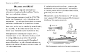
... an antenna mount to the receiver may be controlled by an on/off switch, such as a switch on and off. Before permanently installing and wiring the GPS 17, temporarily place the unit in doubt, seek professional assistance. When a you find a problem with your Garmin dealer or a marine retailer for a suitable mount for GPS units are...
... an antenna mount to the receiver may be controlled by an on/off switch, such as a switch on and off. Before permanently installing and wiring the GPS 17, temporarily place the unit in doubt, seek professional assistance. When a you find a problem with your Garmin dealer or a marine retailer for a suitable mount for GPS units are...
Installation Guide
Page 7
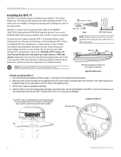
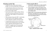
... a template, punch a hole in all other power lines. • As a general rule, mount the receiver at each marked location. 3. Align the GPS 17 over the three holes and fasten the M4 screws. GPS 17 Installation Guide MOUNTING THE GPS 17 To flush mount the GPS 17: 1. Use the template to mark the hole locations on a mast, as...
... a template, punch a hole in all other power lines. • As a general rule, mount the receiver at each marked location. 3. Align the GPS 17 over the three holes and fasten the M4 screws. GPS 17 Installation Guide MOUNTING THE GPS 17 To flush mount the GPS 17: 1. Use the template to mark the hole locations on a mast, as...

Installation Guide
Page 8
... Align the tab on the pole to the base. Screw the GPS 17 onto the mount. Fill the remaining gap in the vertical slot along the side of the base of the Mount 4 GPS 17 Installation Guide Thread the cable though the pole mount. 2. Use the enclosed screws to secure the pole to the ...notch on the base. 3. MOUNTING THE GPS 17 To attach the enclosed pole...
... Align the tab on the pole to the base. Screw the GPS 17 onto the mount. Fill the remaining gap in the vertical slot along the side of the base of the Mount 4 GPS 17 Installation Guide Thread the cable though the pole mount. 2. Use the enclosed screws to secure the pole to the ...notch on the base. 3. MOUNTING THE GPS 17 To attach the enclosed pole...

Installation Guide
Page 9
...• Excessively twisting, straining or bending the cable. When routing the power/data cable, try to pass through the mount and screw the GPS 17 onto the mount. 4. Drill a hole large enough for the cable to avoid the following things: • Sharp edges that can ...the desire location and mark the approximate center of the mount 2. Figure 4: Running the Cable Through the Mount GPS 17 Installation Guide 5 Slide the cable through at the marked location. 3. To mount the GPS 17 with cable through mount: 1. MOUNTING THE GPS 17 Routing the Cable You can cut the cable. ...
...• Excessively twisting, straining or bending the cable. When routing the power/data cable, try to pass through the mount and screw the GPS 17 onto the mount. 4. Drill a hole large enough for the cable to avoid the following things: • Sharp edges that can ...the desire location and mark the approximate center of the mount 2. Figure 4: Running the Cable Through the Mount GPS 17 Installation Guide 5 Slide the cable through at the marked location. 3. To mount the GPS 17 with cable through mount: 1. MOUNTING THE GPS 17 Routing the Cable You can cut the cable. ...

Installation Guide
Page 10
... for these items. 54 3 21 98 76 DB-9 Female Serial Connector 13 7 3 21 25 14 DB-25 Female Serial Connector Garmin recommends that the GPS 17 and the receiving device share the same ground. You need a DB-9 or DB-25 serial connector (normally female) if you install a 1A fuse ...on the power (+) line of the receiving device. This ground connection acts as the (signal) Return line. WIRING THE GPS 17 WIRING THE GPS 17 After mounting the GPS 17 in the desired location, connect the wiring. Black: Ground (Power (-) and Data Signal ...
... for these items. 54 3 21 98 76 DB-9 Female Serial Connector 13 7 3 21 25 14 DB-25 Female Serial Connector Garmin recommends that the GPS 17 and the receiving device share the same ground. You need a DB-9 or DB-25 serial connector (normally female) if you install a 1A fuse ...on the power (+) line of the receiving device. This ground connection acts as the (signal) Return line. WIRING THE GPS 17 WIRING THE GPS 17 After mounting the GPS 17 in the desired location, connect the wiring. Black: Ground (Power (-) and Data Signal ...
Technical Specifications
Page 3
...1.7.1.6 GPS 17HVS Thread Specifications 5 1.7.2 Electrical Characteristics ...5 1.7.2.1 Input Voltage ...5 1.7.2.2 Input Current ...5 1.7.2.3 Standby Current...5 1.7.2.4 GPS Receiver Sensitivity 5 1.7.3 Environmental Characteristics 5 1.7.4 GPS Performance...6 1.7.4.1 Receiver...6 1.7.4.2 Acquisition Times...6 1.7.4.3 Sentence Rate ...6 1.7.4.4 Accuracy...6 1.7.5 Interfaces...6 1.7.5.1 Port 1 ...6 1.7.5.2 Port 2 ...6 1.7.5.3 PPS ...6 1.7.5.4 Power Control...6 2 GPS 16/17 Wiring and Pinouts 7 2.1 GPS 16/17 Pinout ...7 2.2 GPS 16/17 Wiring Diagrams...8 3 Mechanical Characteristics & Mounting...
...1.7.1.6 GPS 17HVS Thread Specifications 5 1.7.2 Electrical Characteristics ...5 1.7.2.1 Input Voltage ...5 1.7.2.2 Input Current ...5 1.7.2.3 Standby Current...5 1.7.2.4 GPS Receiver Sensitivity 5 1.7.3 Environmental Characteristics 5 1.7.4 GPS Performance...6 1.7.4.1 Receiver...6 1.7.4.2 Acquisition Times...6 1.7.4.3 Sentence Rate ...6 1.7.4.4 Accuracy...6 1.7.5 Interfaces...6 1.7.5.1 Port 1 ...6 1.7.5.2 Port 2 ...6 1.7.5.3 PPS ...6 1.7.5.4 Power Control...6 2 GPS 16/17 Wiring and Pinouts 7 2.1 GPS 16/17 Pinout ...7 2.2 GPS 16/17 Wiring Diagrams...8 3 Mechanical Characteristics & Mounting...
Technical Specifications
Page 4
... Datums 20 Appendix B: Binary Phase Output Format 23 Position Record ...23 Receiver Measurement Record ...24 Sample C Code...25 Appendix C: Ephemeris Data download (Programming Example 26 Synopsis ...26 Garmin Binary Format Review ...26 Ephemeris Download Procedure ...27 TX Packet: Ephemeris ... Comm Menu...32 Config Menu ...32 View Menu...33 Help Menu...33 LIST OF TABLES AND FIGURES GPS 16LVS & 16HVS ...4 GPS17HVS with Pole Mount ...4 GPS 17HVS Flush Mount ...4 Table 1: GPS 16/17 Wire Pinout ...7 Figure 1: Computer Serial Port Interconnection...8 Figure 2: PDA Serial Port Interconnection...8...
... Datums 20 Appendix B: Binary Phase Output Format 23 Position Record ...23 Receiver Measurement Record ...24 Sample C Code...25 Appendix C: Ephemeris Data download (Programming Example 26 Synopsis ...26 Garmin Binary Format Review ...26 Ephemeris Download Procedure ...27 TX Packet: Ephemeris ... Comm Menu...32 Config Menu ...32 View Menu...33 Help Menu...33 LIST OF TABLES AND FIGURES GPS 16LVS & 16HVS ...4 GPS17HVS with Pole Mount ...4 GPS 17HVS Flush Mount ...4 Table 1: GPS 16/17 Wire Pinout ...7 Figure 1: Computer Serial Port Interconnection...8 Figure 2: PDA Serial Port Interconnection...8...
Technical Specifications
Page 7
...8226; May be remotely mounted in an out-of-the-way location. • Receiver position information can be supplied by Garmin to retain critical data such as the dynamics requirements of high-performance aircraft. Pulse width is configurable in the GPS 16HVS and GPS 17HVS. • FLASH-based...Waterproof design allows continuous exposure to the prevailing weather conditions at most locations. • GPS 17HVS can be displayed directly on the proven technology found in other Garmin 12-channel GPS receivers, the GPS 16/17 tracks up to 12 satellites at a time while providing fast time-to ...
...8226; May be remotely mounted in an out-of-the-way location. • Receiver position information can be supplied by Garmin to retain critical data such as the dynamics requirements of high-performance aircraft. Pulse width is configurable in the GPS 16HVS and GPS 17HVS. • FLASH-based...Waterproof design allows continuous exposure to the prevailing weather conditions at most locations. • GPS 17HVS can be displayed directly on the proven technology found in other Garmin 12-channel GPS receivers, the GPS 16/17 tracks up to 12 satellites at a time while providing fast time-to ...

Technical Specifications
Page 8
GPS 17HVS can also use the GPS17HVS on the enclosed 1" pole mount (also called a marine mount). GPS17HVS with a white logo. A You can be flush mounted or pole mounted on a standard one-inch, 14 threads-perinch marine mount. 1.6 GPS 16/17 Series There are several different products in the GPS 16/17 product series, as described below. 1.6.1 GPS 16LVS & 16HVS Both the GPS 16LVS and GPS 16HVS are black with Pole Mount 190-00228-21 GPS 17HVS Flush Mount GPS 16/17 Technical Specifications Page 4 Rev. GPS 16LVS & 16HVS 1.6.2 GPS 17HVS The GPS 17HVS is white with a blue logo.
GPS 17HVS can also use the GPS17HVS on the enclosed 1" pole mount (also called a marine mount). GPS17HVS with a white logo. A You can be flush mounted or pole mounted on a standard one-inch, 14 threads-perinch marine mount. 1.6 GPS 16/17 Series There are several different products in the GPS 16/17 product series, as described below. 1.6.1 GPS 16LVS & 16HVS Both the GPS 16LVS and GPS 16HVS are black with Pole Mount 190-00228-21 GPS 17HVS Flush Mount GPS 16/17 Technical Specifications Page 4 Rev. GPS 16LVS & 16HVS 1.6.2 GPS 17HVS The GPS 17HVS is white with a blue logo.

Technical Specifications
Page 9
... cable: 11.7 oz (332 g) • GPS 16LVS & 16HVS cable alone: 5.3 oz (151 g) • GPS 17HVS only: 7.1 oz (201 g) • GPS 17HVS with 30-foot cable: 16.8 oz (465 g) • GPS 17HVS with pole mount adapter & cable: 18.2 oz (516 g) • GPS 17HVS pole mount adapter alone: 1.4 oz (40 g) • GPS 17HVS cable alone: 9.7 oz (275 g) 1.7.1.3 Cable • GPS 16LVS & 16HVS: Black PVC-jacketed, 5-meter...
... cable: 11.7 oz (332 g) • GPS 16LVS & 16HVS cable alone: 5.3 oz (151 g) • GPS 17HVS only: 7.1 oz (201 g) • GPS 17HVS with 30-foot cable: 16.8 oz (465 g) • GPS 17HVS with pole mount adapter & cable: 18.2 oz (516 g) • GPS 17HVS pole mount adapter alone: 1.4 oz (40 g) • GPS 17HVS cable alone: 9.7 oz (275 g) 1.7.1.3 Cable • GPS 16LVS & 16HVS: Black PVC-jacketed, 5-meter...

Technical Specifications
Page 14
A 3.2 GPS 17 3.60 inches (91.5 mm) 0.27 inches [7 mm] M4 Thread Fits on a standard oneinch, 14 threads-per-inch marine mount. 3.58 inches [91 mm] Figure 5: GPS 17 Dimensions 190-00228-21 GPS 16/17 Technical Specifications Page 10 Rev.
A 3.2 GPS 17 3.60 inches (91.5 mm) 0.27 inches [7 mm] M4 Thread Fits on a standard oneinch, 14 threads-per-inch marine mount. 3.58 inches [91 mm] Figure 5: GPS 17 Dimensions 190-00228-21 GPS 16/17 Technical Specifications Page 10 Rev.

Technical Specifications
Page 15
Figure 6: GPS 17 Attaching to the Included Pole Mount 3.3 GPS 16 Optional Magnetic Mount Magnetic Mount M4 Flat Head Screws (3 each) Figure 7: Optional GPS 16 Magnetic Mount 190-00228-21 GPS 16/17 Technical Specifications Page 11 Rev. A
Figure 6: GPS 17 Attaching to the Included Pole Mount 3.3 GPS 16 Optional Magnetic Mount Magnetic Mount M4 Flat Head Screws (3 each) Figure 7: Optional GPS 16 Magnetic Mount 190-00228-21 GPS 16/17 Technical Specifications Page 11 Rev. A

