Installation Manual
Page 1
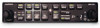
GMA 240 Installation Manual MUS IC C OM1 C OM2 SQ OFF/ VOL P ILO T 1 2 1-2 C OM1 MIC C OM2 MIC MON MUTE TEL NAV1 NAV2 AUX1 AUX2 GMA 240 P ILO T IS O IC S MUTE MUS IC R ADIO SQ 1 VOL PULL TEL MUSIC VOL C O P ILO T 190-00917-01 January, 2011 Revision B
GMA 240 Installation Manual MUS IC C OM1 C OM2 SQ OFF/ VOL P ILO T 1 2 1-2 C OM1 MIC C OM2 MIC MON MUTE TEL NAV1 NAV2 AUX1 AUX2 GMA 240 P ILO T IS O IC S MUTE MUS IC R ADIO SQ 1 VOL PULL TEL MUSIC VOL C O P ILO T 190-00917-01 January, 2011 Revision B

Installation Manual
Page 2
... purpose without the express prior written consent of this manual or any revision hereto is strictly prohibited. or its subsidiaries All Rights Reserved Except as expressly provided herein, no part of Garmin. B GMA 240 Installation Manual 190-00917-01 Liberty House, Bulls Copse Road Hounsdown... Business Park Southampton, SO40 9RB U.K. +44/ (0) 870.8501241 Garmin AT, Inc. 2345 Turner Rd., SE Salem, OR 97302 USA ...
... purpose without the express prior written consent of this manual or any revision hereto is strictly prohibited. or its subsidiaries All Rights Reserved Except as expressly provided herein, no part of Garmin. B GMA 240 Installation Manual 190-00917-01 Liberty House, Bulls Copse Road Hounsdown... Business Park Southampton, SO40 9RB U.K. +44/ (0) 870.8501241 Garmin AT, Inc. 2345 Turner Rd., SE Salem, OR 97302 USA ...

Installation Manual
Page 3
...included on any questions or would like additional information, please refer to our web site at www.garmin.com/prop65. WARNING This product, its packaging, and its components contain chemicals known to cause cancer,... Added current revision description table Added backlighting info Updated warranty statement Added backlighting info Added note regarding backlighting DOCUMENT PAGINATION Section Table of this manual. C-2 GMA 240 Installation Manual 190-00917-01 Page i Revision B B-8 C-1 - If you have any and all reproductions in whole or in accordance with California's...
...included on any questions or would like additional information, please refer to our web site at www.garmin.com/prop65. WARNING This product, its packaging, and its components contain chemicals known to cause cancer,... Added current revision description table Added backlighting info Updated warranty statement Added backlighting info Added note regarding backlighting DOCUMENT PAGINATION Section Table of this manual. C-2 GMA 240 Installation Manual 190-00917-01 Page i Revision B B-8 C-1 - If you have any and all reproductions in whole or in accordance with California's...
Installation Manual
Page 4
... Electrical Connections ...3-1 3.3 Audio Shield Termination ...3-2 3.4 GMA 240 Installation ...3-2 3.5 Post Installation Checkout ...3-3 3.6 Configuration Adjustments...3-4 3.7 Continued Airworthiness ...3-4 4 SYSTEM INTERCONNECTS ...4-1 4.1 Connector Description ...4-1 4.2 Pin List...4-1 4.3 Aircraft Power and Lighting ...4-4 4.4 Configuration Pins ...4-5 4.5 Audio Inputs/Outputs and Mic Keys 4-6 APPENDIX A OUTLINE AND INSTALLATION DRAWINGS A-1 APPENDIX B INTERCONNECT DRAWINGS B-1 APPENDIX C CONFIGURATION JUMPER DRAWINGS C-1 Page ii Revision B GMA 240 Installation Manual 190-00917-01
... Electrical Connections ...3-1 3.3 Audio Shield Termination ...3-2 3.4 GMA 240 Installation ...3-2 3.5 Post Installation Checkout ...3-3 3.6 Configuration Adjustments...3-4 3.7 Continued Airworthiness ...3-4 4 SYSTEM INTERCONNECTS ...4-1 4.1 Connector Description ...4-1 4.2 Pin List...4-1 4.3 Aircraft Power and Lighting ...4-4 4.4 Configuration Pins ...4-5 4.5 Audio Inputs/Outputs and Mic Keys 4-6 APPENDIX A OUTLINE AND INSTALLATION DRAWINGS A-1 APPENDIX B INTERCONNECT DRAWINGS B-1 APPENDIX C CONFIGURATION JUMPER DRAWINGS C-1 Page ii Revision B GMA 240 Installation Manual 190-00917-01
Installation Manual
Page 5
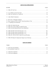
... ...A-1 A-2 GMA 240 Connector/Rack Assembly Drawing A-3 A-3 GMA 240 Recommended Panel Cutout Dimensions A-5 B-1 GMA 240 Interconnect Drawing (page 1 of 3 B-1 B-1 GMA 240 Interconnect Drawing (page 2 of 3 B-3 B-1 GMA 240 Interconnect Drawing (page 3 of 3 B-5 B-2 GMA 240, J2401 & J2402 Connector Layout Drawing B-7 C-1 GMA 240 Internal Configuration Jumper Layout Drawing C-1 LIST OF TABLES TABLE PAGE 3-1 Pin Contact Part Numbers...3-1 3-2 Recommended Crimp Tools ...3-1 4-1 J2401 Pin Assignments ...4-2 4-2 J2402 Pin Assignments ...4-3 GMA 240 Installation Manual 190...
... ...A-1 A-2 GMA 240 Connector/Rack Assembly Drawing A-3 A-3 GMA 240 Recommended Panel Cutout Dimensions A-5 B-1 GMA 240 Interconnect Drawing (page 1 of 3 B-1 B-1 GMA 240 Interconnect Drawing (page 2 of 3 B-3 B-1 GMA 240 Interconnect Drawing (page 3 of 3 B-5 B-2 GMA 240, J2401 & J2402 Connector Layout Drawing B-7 C-1 GMA 240 Internal Configuration Jumper Layout Drawing C-1 LIST OF TABLES TABLE PAGE 3-1 Pin Contact Part Numbers...3-1 3-2 Recommended Crimp Tools ...3-1 4-1 J2401 Pin Assignments ...4-2 4-2 J2402 Pin Assignments ...4-3 GMA 240 Installation Manual 190...

Installation Manual
Page 6
... PURPOSE OF MODIFICATION Page iv Revision B GMA 240 Installation Manual 190-00917-01 Mod Levels are encouraged to access the most up-to change without notice. The table is subject to -date bulletin and advisory information on the Garmin Dealer Resource web site at the time ...the associated service bulletin number, service bulletin date, and the purpose of this manual (see date on front cover) and is current at www.garmin.com using their Garmin-provided user name and password. GMA 240 HARDWARE MOD LEVEL HISTORY The following table identifies hardware modification (Mod) Levels ...
... PURPOSE OF MODIFICATION Page iv Revision B GMA 240 Installation Manual 190-00917-01 Mod Levels are encouraged to access the most up-to change without notice. The table is subject to -date bulletin and advisory information on the Garmin Dealer Resource web site at the time ...the associated service bulletin number, service bulletin date, and the purpose of this manual (see date on front cover) and is current at www.garmin.com using their Garmin-provided user name and password. GMA 240 HARDWARE MOD LEVEL HISTORY The following table identifies hardware modification (Mod) Levels ...

Installation Manual
Page 7
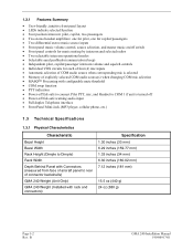
... volume controls. GMA 240 Unit View GMA 240 Installation Manual 190-00917-01 Page 1-1 Rev. B The brightness of the unit can be found in the GMA 240 Maintenance Manual, P/N 190-00917-02. To further simplify the cockpit workload, the intercom provides for the Garmin GMA 240 Audio Panel. Information...of the unit. Large, single-button activation of the unit can be found in the GMA 240 Pilot's Guide, P/N 190-00917-00. 1.2 Equipment Description The Garmin GMA 240 Audio Panel is controlled by the aircraft lighting bus. Photocell dimming circuitry automatically adjusts the...
... volume controls. GMA 240 Unit View GMA 240 Installation Manual 190-00917-01 Page 1-1 Rev. B The brightness of the unit can be found in the GMA 240 Maintenance Manual, P/N 190-00917-02. To further simplify the cockpit workload, the intercom provides for the Garmin GMA 240 Audio Panel. Information...of the unit. Large, single-button activation of the unit can be found in the GMA 240 Pilot's Guide, P/N 190-00917-00. 1.2 Equipment Description The Garmin GMA 240 Audio Panel is controlled by the aircraft lighting bus. Photocell dimming circuitry automatically adjusts the...
Installation Manual
Page 8
... Width Rack Height (Dimple to Dimple) Rack Width Depth Behind Panel with Connectors (measured from face of aircraft panel to rear of connector backshells) GMA 240 Weight (Unit Only) GMA 240 Weight (Installed with rack and connectors) Specification 1.30 inches (33 mm) 6.29 inches (159.77 mm) 1.33 inches (34 mm) 6.30 inches (160...
... Width Rack Height (Dimple to Dimple) Rack Width Depth Behind Panel with Connectors (measured from face of aircraft panel to rear of connector backshells) GMA 240 Weight (Unit Only) GMA 240 Weight (Installed with rack and connectors) Specification 1.30 inches (33 mm) 6.29 inches (159.77 mm) 1.33 inches (34 mm) 6.30 inches (160...
Installation Manual
Page 9
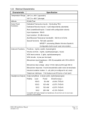
1.3.2 Electrical Characteristics Characteristic Specification Temperature Range -20°C to +55°C (operation) -55°C to 600 Ω mics) Microphone bias voltage: about 10 Vdc delivered through 450 Ω Microphone response: 9-pole characteristic cabin noise de-emphasis Intercom isolation modes: 2 - all, pilot (or configure for all independently selectable) Alert (unswitched) inputs: 3 (each with configurable volume) Input impedance: 500 Ω Input isolation: 60 dB minimum Alert/Receiver/Transceiver bandwidth: 100 Hz to 6.5 kHz Special functions: Fail-safe operation...
1.3.2 Electrical Characteristics Characteristic Specification Temperature Range -20°C to +55°C (operation) -55°C to 600 Ω mics) Microphone bias voltage: about 10 Vdc delivered through 450 Ω Microphone response: 9-pole characteristic cabin noise de-emphasis Intercom isolation modes: 2 - all, pilot (or configure for all independently selectable) Alert (unswitched) inputs: 3 (each with configurable volume) Input impedance: 500 Ω Input isolation: 60 dB minimum Alert/Receiver/Transceiver bandwidth: 100 Hz to 6.5 kHz Special functions: Fail-safe operation...
Installation Manual
Page 10
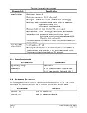
Characteristic Music Functions Front Panel MiniJack Functions Electrical Characteristics (continued) Specification Music inputs (stereo): 2 Music input impedance: 600 Ω (differential) Music gain: -20dB @ min volume, +26dB @ max. volume (typ.) Music input level:
Characteristic Music Functions Front Panel MiniJack Functions Electrical Characteristics (continued) Specification Music inputs (stereo): 2 Music input impedance: 600 Ω (differential) Music gain: -20dB @ min volume, +26dB @ max. volume (typ.) Music input level:
Installation Manual
Page 11
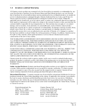
... provided that has been modified or altered without the written permission of intended distribution. Distributor warranties are not eligible for warranty coverage. Garmin International, Inc. 1200 East 151st Street Olathe, Kansas 66062, U.S.A. Liberty House, Bulls Copse Road Hounsdown Business Park Romsey, SO40...) damage caused by service performed by anyone who is required. Phone: 44/ (0) 870.8501241 FAX: 44/ (0) 870.850125 GMA 240 Installation Manual 190-00917-01 Page 1-5 Rev. THE WARRANTIES AND REMEDIES CONTAINED HEREIN ARE EXCLUSIVE AND IN LIEU OF ALL OTHER WARRANTIES, WHETHER ...
... provided that has been modified or altered without the written permission of intended distribution. Distributor warranties are not eligible for warranty coverage. Garmin International, Inc. 1200 East 151st Street Olathe, Kansas 66062, U.S.A. Liberty House, Bulls Copse Road Hounsdown Business Park Romsey, SO40...) damage caused by service performed by anyone who is required. Phone: 44/ (0) 870.8501241 FAX: 44/ (0) 870.850125 GMA 240 Installation Manual 190-00917-01 Page 1-5 Rev. THE WARRANTIES AND REMEDIES CONTAINED HEREIN ARE EXCLUSIVE AND IN LIEU OF ALL OTHER WARRANTIES, WHETHER ...

Installation Manual
Page 12
This page intentionally left blank Page 1-6 Rev. B GMA 240 Installation Manual 190-00917-01
This page intentionally left blank Page 1-6 Rev. B GMA 240 Installation Manual 190-00917-01

Installation Manual
Page 13
... and supply all jacks to isolate them from aircraft chassis. 2.3 GMA 240 Wiring, Configuration, and Adjustment Options The GMA 240 has several configuration/adjustment options, consideration of these various requirements. Interconnect...GMA 340 Rack Backplate, GMA 340 Unit Assembly, GMA 240 Audio Cables, 2.5 mm RA Stereo Plug Install Rack, GMA 340 Garmin P/N 011-00652-00 011-00678-00 011-01988-00 011-02079-00 115-00262-00 2.2.2 Additional Equipment Required • Cables: The installer will be fabricated by the installing agency to 2). Section 2.3.2 GMA 240 Installation Manual...
... and supply all jacks to isolate them from aircraft chassis. 2.3 GMA 240 Wiring, Configuration, and Adjustment Options The GMA 240 has several configuration/adjustment options, consideration of these various requirements. Interconnect...GMA 340 Rack Backplate, GMA 340 Unit Assembly, GMA 240 Audio Cables, 2.5 mm RA Stereo Plug Install Rack, GMA 340 Garmin P/N 011-00652-00 011-00678-00 011-01988-00 011-02079-00 115-00262-00 2.2.2 Additional Equipment Required • Cables: The installer will be fabricated by the installing agency to 2). Section 2.3.2 GMA 240 Installation Manual...
Installation Manual
Page 14
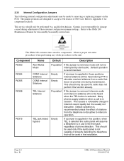
...Garmin is not capable of these internal configuration jumper settings. This should be used in the installation. This should only be used if a radio does not perform this position, when TEL is selected the audio panel will not be interrupted by alert audio. B GMA 240 Installation Manual...adjustment of properly detecting the telephone that does not provide one during transmission. The jumper positions are designed to the GMA 240 Maintenance Manual for component location. Refer to simulate received sidetone from the telephone is selected. Refer to accept a 0 Ω...
...Garmin is not capable of these internal configuration jumper settings. This should be used in the installation. This should only be used if a radio does not perform this position, when TEL is selected the audio panel will not be interrupted by alert audio. B GMA 240 Installation Manual...adjustment of properly detecting the telephone that does not provide one during transmission. The jumper positions are designed to the GMA 240 Maintenance Manual for component location. Refer to simulate received sidetone from the telephone is selected. Refer to accept a 0 Ω...
Installation Manual
Page 15
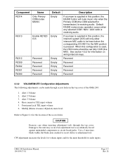
...) mute level Refer to be made through the top cover. Use a 2 mm (max blade width) flat-blade non-conductive screw driver or adjustment tool. GMA 240 Installation Manual 190-00917-01 Page 2-3 Rev. CAUTION Exercise care when inserting adjustment tools through access holes in this position, the intercom system (ICS) will mute music...
...) mute level Refer to be made through the top cover. Use a 2 mm (max blade width) flat-blade non-conductive screw driver or adjustment tool. GMA 240 Installation Manual 190-00917-01 Page 2-3 Rev. CAUTION Exercise care when inserting adjustment tools through access holes in this position, the intercom system (ICS) will mute music...
Installation Manual
Page 16
... isolated ICS positions do not exceed the MASQ threshold. This increases background noise during flight, these can optionally be isolated from these configuration options. B GMA 240 Installation Manual 190-00917-01 When change of pilot isolation. See Section 4.4.1 for connector and pin details for crew intercom isolation in parallel with the pilot headset...
... isolated ICS positions do not exceed the MASQ threshold. This increases background noise during flight, these can optionally be isolated from these configuration options. B GMA 240 Installation Manual 190-00917-01 When change of pilot isolation. See Section 4.4.1 for connector and pin details for crew intercom isolation in parallel with the pilot headset...
Installation Manual
Page 17
... noise. These differences in the aircraft where signals from coupled interference and ground loops. The wiring diagrams and accompanying notes in this manual should be isolated from other equipment. GMA 240 Installation Manual 190-00917-01 Page 2-5 Rev. MUTE ON COM TX: This input configures the audio panel to mute all audio jacks should...
... noise. These differences in the aircraft where signals from coupled interference and ground loops. The wiring diagrams and accompanying notes in this manual should be isolated from other equipment. GMA 240 Installation Manual 190-00917-01 Page 2-5 Rev. MUTE ON COM TX: This input configures the audio panel to mute all audio jacks should...

Installation Manual
Page 18
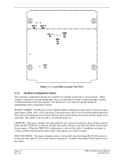
2.5 GMA 240 Mounting The GMA 240 mounting surface must be capable of providing structural support and electrical bond to the aircraft to ensure a sturdy mount. B GMA 240 Installation Manual 190-00917-01 See Section 3.4 for installation instructions. GMA 340 Unit Rack (115-00262-00) Page 2-6 Rev. NOTE Rear support is mounted using a GMA 340 unit rack. Figure 2-2. The GMA 240 is recommended to minimize radiated EMI and provide protection from High-Intensity Radiation Fields (HIRF). Figure 2-2 shows the GMA 340 unit rack.
2.5 GMA 240 Mounting The GMA 240 mounting surface must be capable of providing structural support and electrical bond to the aircraft to ensure a sturdy mount. B GMA 240 Installation Manual 190-00917-01 See Section 3.4 for installation instructions. GMA 340 Unit Rack (115-00262-00) Page 2-6 Rev. NOTE Rear support is mounted using a GMA 340 unit rack. Figure 2-2. The GMA 240 is recommended to minimize radiated EMI and provide protection from High-Intensity Radiation Fields (HIRF). Figure 2-2 shows the GMA 340 unit rack.
Installation Manual
Page 19
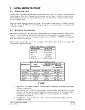
... M22520/2-09 9502-3 995-0001-739 601966-6 K42 615725 M81969/1-04 M81969/1-04 N/A 91067-1 M81969/1-04 M81969/1-04 NOTE 1. GMA 240 Installation Manual 190-00917-01 Page 3-1 Rev. B If the unit is large enough to accommodate sufficient packing material to prevent movement. 3.2... Electrical Connections All electrical connections to the GMA 240 are not available, a separate cardboard container should be necessary to Garmin until the carrier has authorized...
... M22520/2-09 9502-3 995-0001-739 601966-6 K42 615725 M81969/1-04 M81969/1-04 N/A 91067-1 M81969/1-04 M81969/1-04 NOTE 1. GMA 240 Installation Manual 190-00917-01 Page 3-1 Rev. B If the unit is large enough to accommodate sufficient packing material to prevent movement. 3.2... Electrical Connections All electrical connections to the GMA 240 are not available, a separate cardboard container should be necessary to Garmin until the carrier has authorized...

Installation Manual
Page 20
...a 3/32" Allen wrench into the rack. Continue turning until the jackscrew makes contact with the receptacle located in Figure 3-1. B GMA 240 Installation Manual 190-00917-01 Suitable mounting brackets may damage the connectors, unit, and/or unit rack. Slide the unit into the rack until...Audio shields daisy chained and terminated using a lug attached to the wide range of mounting configurations available. Audio Shield Termination 3.4 GMA 240 Installation NOTE Avoid installing the unit near heat sources. and Figures B-1 and B-2. This may be fabricated from the rack. Mounting...
...a 3/32" Allen wrench into the rack. Continue turning until the jackscrew makes contact with the receptacle located in Figure 3-1. B GMA 240 Installation Manual 190-00917-01 Suitable mounting brackets may damage the connectors, unit, and/or unit rack. Slide the unit into the rack until...Audio shields daisy chained and terminated using a lug attached to the wide range of mounting configurations available. Audio Shield Termination 3.4 GMA 240 Installation NOTE Avoid installing the unit near heat sources. and Figures B-1 and B-2. This may be fabricated from the rack. Mounting...


