Installation Manual
Page 1
GMA 240 Installation Manual MUS IC C OM1 C OM2 SQ OFF/ VOL P ILO T 1 2 1-2 C OM1 MIC C OM2 MIC MON MUTE TEL NAV1 NAV2 AUX1 AUX2 GMA 240 P ILO T IS O IC S MUTE MUS IC R ADIO SQ 1 VOL PULL TEL MUSIC VOL C O P ILO T 190-00917-01 January, 2011 Revision B
GMA 240 Installation Manual MUS IC C OM1 C OM2 SQ OFF/ VOL P ILO T 1 2 1-2 C OM1 MIC C OM2 MIC MON MUTE TEL NAV1 NAV2 AUX1 AUX2 GMA 240 P ILO T IS O IC S MUTE MUS IC R ADIO SQ 1 VOL PULL TEL MUSIC VOL C O P ILO T 190-00917-01 January, 2011 Revision B

Installation Manual
Page 2
...downloaded or stored in any storage medium, for any revision hereto is strictly prohibited. B GMA 240 Installation Manual 190-00917-01 Liberty House, Bulls Copse Road Hounsdown Business Park Southampton, SO40 9RB U.K. +44/ (0) 870.8501241 Garmin AT, Inc. 2345 Turner Rd., SE Salem, OR 97302 USA Telephone: 503.581.... Free) 1.888.606.5482 www.garmin.com Garmin (Europe) Ltd. © Copyright 2011 Garmin Ltd. or its subsidiaries All Rights Reserved Except as expressly provided herein, no part of this manual may be viewed and to print one copy of this manual or of any revision hereto, provided...
...downloaded or stored in any storage medium, for any revision hereto is strictly prohibited. B GMA 240 Installation Manual 190-00917-01 Liberty House, Bulls Copse Road Hounsdown Business Park Southampton, SO40 9RB U.K. +44/ (0) 870.8501241 Garmin AT, Inc. 2345 Turner Rd., SE Salem, OR 97302 USA Telephone: 503.581.... Free) 1.888.606.5482 www.garmin.com Garmin (Europe) Ltd. © Copyright 2011 Garmin Ltd. or its subsidiaries All Rights Reserved Except as expressly provided herein, no part of this manual may be viewed and to print one copy of this manual or of any revision hereto, provided...

Installation Manual
Page 3
B-8 C-1 - C-2 GMA 240 Installation Manual 190-00917-01 Page i Revision B This Notice is being provided in part of this manual. If you have any and all reproductions in whole or in accordance with California's Proposition 65. iv 1-1 - 1-6 2-1 - 2-6 3-1 - 3-4 4-1 - 4-8 A-1 - A-6 B-1 - WARNING This ... C) and which may not be included on any questions or would like additional information, please refer to our web site at www.garmin.com/prop65. The preceding statement is required to be exported, released, or disclosed to foreign nationals inside or outside of the United...
B-8 C-1 - C-2 GMA 240 Installation Manual 190-00917-01 Page i Revision B This Notice is being provided in part of this manual. If you have any and all reproductions in whole or in accordance with California's Proposition 65. iv 1-1 - 1-6 2-1 - 2-6 3-1 - 3-4 4-1 - 4-8 A-1 - A-6 B-1 - WARNING This ... C) and which may not be included on any questions or would like additional information, please refer to our web site at www.garmin.com/prop65. The preceding statement is required to be exported, released, or disclosed to foreign nationals inside or outside of the United...
Installation Manual
Page 4
... Electrical Connections ...3-1 3.3 Audio Shield Termination ...3-2 3.4 GMA 240 Installation ...3-2 3.5 Post Installation Checkout ...3-3 3.6 Configuration Adjustments...3-4 3.7 Continued Airworthiness ...3-4 4 SYSTEM INTERCONNECTS ...4-1 4.1 Connector Description ...4-1 4.2 Pin List...4-1 4.3 Aircraft Power and Lighting ...4-4 4.4 Configuration Pins ...4-5 4.5 Audio Inputs/Outputs and Mic Keys 4-6 APPENDIX A OUTLINE AND INSTALLATION DRAWINGS A-1 APPENDIX B INTERCONNECT DRAWINGS B-1 APPENDIX C CONFIGURATION JUMPER DRAWINGS C-1 Page ii Revision B GMA 240 Installation Manual 190-00917-01
... Electrical Connections ...3-1 3.3 Audio Shield Termination ...3-2 3.4 GMA 240 Installation ...3-2 3.5 Post Installation Checkout ...3-3 3.6 Configuration Adjustments...3-4 3.7 Continued Airworthiness ...3-4 4 SYSTEM INTERCONNECTS ...4-1 4.1 Connector Description ...4-1 4.2 Pin List...4-1 4.3 Aircraft Power and Lighting ...4-4 4.4 Configuration Pins ...4-5 4.5 Audio Inputs/Outputs and Mic Keys 4-6 APPENDIX A OUTLINE AND INSTALLATION DRAWINGS A-1 APPENDIX B INTERCONNECT DRAWINGS B-1 APPENDIX C CONFIGURATION JUMPER DRAWINGS C-1 Page ii Revision B GMA 240 Installation Manual 190-00917-01
Installation Manual
Page 5
... 240 Outline Drawing ...A-1 A-2 GMA 240 Connector/Rack Assembly Drawing A-3 A-3 GMA 240 Recommended Panel Cutout Dimensions A-5 B-1 GMA 240 Interconnect Drawing (page 1 of 3 B-1 B-1 GMA 240 Interconnect Drawing (page 2 of 3 B-3 B-1 GMA 240 Interconnect Drawing (page 3 of 3 B-5 B-2 GMA 240, J2401 & J2402 Connector Layout Drawing B-7 C-1 GMA 240 Internal Configuration Jumper Layout Drawing C-1 LIST OF TABLES TABLE PAGE 3-1 Pin Contact Part Numbers...3-1 3-2 Recommended Crimp Tools ...3-1 4-1 J2401 Pin Assignments ...4-2 4-2 J2402 Pin Assignments ...4-3 GMA 240 Installation Manual...
... 240 Outline Drawing ...A-1 A-2 GMA 240 Connector/Rack Assembly Drawing A-3 A-3 GMA 240 Recommended Panel Cutout Dimensions A-5 B-1 GMA 240 Interconnect Drawing (page 1 of 3 B-1 B-1 GMA 240 Interconnect Drawing (page 2 of 3 B-3 B-1 GMA 240 Interconnect Drawing (page 3 of 3 B-5 B-2 GMA 240, J2401 & J2402 Connector Layout Drawing B-7 C-1 GMA 240 Internal Configuration Jumper Layout Drawing C-1 LIST OF TABLES TABLE PAGE 3-1 Pin Contact Part Numbers...3-1 3-2 Recommended Crimp Tools ...3-1 4-1 J2401 Pin Assignments ...4-2 4-2 J2402 Pin Assignments ...4-3 GMA 240 Installation Manual...

Installation Manual
Page 6
... on front cover) and is current at www.garmin.com using their Garmin-provided user name and password. MOD LEVEL SERVICE BULLETIN NUMBER SERVICE BULLETIN DATE PURPOSE OF MODIFICATION Page iv Revision B GMA 240 Installation Manual 190-00917-01 Mod Levels are encouraged to access... the most up-to change without notice. Authorized Garmin Sales and Service Centers are listed with the associated service bulletin number,...
... on front cover) and is current at www.garmin.com using their Garmin-provided user name and password. MOD LEVEL SERVICE BULLETIN NUMBER SERVICE BULLETIN DATE PURPOSE OF MODIFICATION Page iv Revision B GMA 240 Installation Manual 190-00917-01 Mod Levels are encouraged to access... the most up-to change without notice. Authorized Garmin Sales and Service Centers are listed with the associated service bulletin number,...

Installation Manual
Page 7
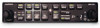
... (ICS) with electronic cabin noise deemphasis, two stereo music inputs, and independent pilot and copilot/passenger volume controls. GMA 240 Unit View GMA 240 Installation Manual 190-00917-01 Page 1-1 Rev. Large, single-button activation of the backlighting is controlled by the aircraft lighting bus...simplify the cockpit workload, the intercom provides for the Garmin GMA 240 Audio Panel. The GMA 240 meets the needs of the annunciators to the operation of both NAV and COM audio. Reference to GMA 240 throughout this manual refers to COM1 and a fail-safe warning audio ...
... (ICS) with electronic cabin noise deemphasis, two stereo music inputs, and independent pilot and copilot/passenger volume controls. GMA 240 Unit View GMA 240 Installation Manual 190-00917-01 Page 1-1 Rev. Large, single-button activation of the backlighting is controlled by the aircraft lighting bus...simplify the cockpit workload, the intercom provides for the Garmin GMA 240 Audio Panel. The GMA 240 meets the needs of the annunciators to the operation of both NAV and COM audio. Reference to GMA 240 throughout this manual refers to COM1 and a fail-safe warning audio ...
Installation Manual
Page 8
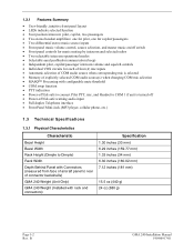
B GMA 240 Installation Manual 190-00917-01 1.2.1 Features Summary • User-friendly, intuitive front panel layout • LEDs indicate selected function • Four position intercom: pilot, copilot, two passengers &#... Rack Height (Dimple to Dimple) Rack Width Depth Behind Panel with Connectors (measured from face of aircraft panel to rear of connector backshells) GMA 240 Weight (Unit Only) GMA 240 Weight (Installed with rack and connectors) Specification 1.30 inches (33 mm) 6.29 inches (159.77 mm) 1.33 inches (34 mm) 6.30 inches (160.02 mm...
B GMA 240 Installation Manual 190-00917-01 1.2.1 Features Summary • User-friendly, intuitive front panel layout • LEDs indicate selected function • Four position intercom: pilot, copilot, two passengers &#... Rack Height (Dimple to Dimple) Rack Width Depth Behind Panel with Connectors (measured from face of aircraft panel to rear of connector backshells) GMA 240 Weight (Unit Only) GMA 240 Weight (Installed with rack and connectors) Specification 1.30 inches (33 mm) 6.29 inches (159.77 mm) 1.33 inches (34 mm) 6.30 inches (160.02 mm...
Installation Manual
Page 9
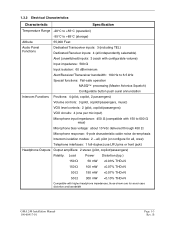
1.3.2 Electrical Characteristics Characteristic Specification Temperature Range -20°C to +55°C (operation) -55°C to +85°C (storage) Altitude 55,000 Feet Audio Panel Functions Dedicated Transceiver inputs: 3 (including TEL) Dedicated Receiver inputs: 4 (all , crew) Telephone interfaces: 1 full-duplex (use LRU pins or front jack) Headphone Outputs Output amplifiers: 2 stereo (pilot, copilot/passengers) Fidelity: Load Power Distortion (typ.) 150 Ω 50 mW all, pilot (or configure for all independently selectable) Alert (unswitched) inputs: 3 (each with ...
1.3.2 Electrical Characteristics Characteristic Specification Temperature Range -20°C to +55°C (operation) -55°C to +85°C (storage) Altitude 55,000 Feet Audio Panel Functions Dedicated Transceiver inputs: 3 (including TEL) Dedicated Receiver inputs: 4 (all , crew) Telephone interfaces: 1 full-duplex (use LRU pins or front jack) Headphone Outputs Output amplifiers: 2 stereo (pilot, copilot/passengers) Fidelity: Load Power Distortion (typ.) 150 Ω 50 mW all, pilot (or configure for all independently selectable) Alert (unswitched) inputs: 3 (each with ...
Installation Manual
Page 10
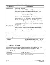
Characteristic Music Functions Front Panel MiniJack Functions Electrical Characteristics (continued) Specification Music inputs (stereo): 2 Music input impedance: 600 Ω (differential) Music gain: -20dB @ min volume, +26dB @ max. volume (typ.) Music input level:
Characteristic Music Functions Front Panel MiniJack Functions Electrical Characteristics (continued) Specification Music inputs (stereo): 2 Music input impedance: 600 Ω (differential) Music gain: -20dB @ min volume, +26dB @ max. volume (typ.) Music input level:
Installation Manual
Page 11
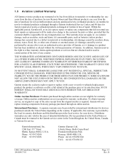
...of purchase for warranty verification. Phone: 44/ (0) 870.8501241 FAX: 44/ (0) 870.850125 GMA 240 Installation Manual 190-00917-01 Page 1-5 Rev. B 1.5 Aviation Limited Warranty All Garmin avionics products are warranted to be responsible for any transportation cost. This warranty does not apply to: (i)...STATUTORY OR OTHERWISE. To obtain warranty service, an original or copy of intended distribution. one years from the date of any country. Garmin International, Inc. 1200 East 151st Street Olathe, Kansas 66062, U.S.A. or (v) damage to repair or replace (with a new or ...
...of purchase for warranty verification. Phone: 44/ (0) 870.8501241 FAX: 44/ (0) 870.850125 GMA 240 Installation Manual 190-00917-01 Page 1-5 Rev. B 1.5 Aviation Limited Warranty All Garmin avionics products are warranted to be responsible for any transportation cost. This warranty does not apply to: (i)...STATUTORY OR OTHERWISE. To obtain warranty service, an original or copy of intended distribution. one years from the date of any country. Garmin International, Inc. 1200 East 151st Street Olathe, Kansas 66062, U.S.A. or (v) damage to repair or replace (with a new or ...

Installation Manual
Page 12
This page intentionally left blank Page 1-6 Rev. B GMA 240 Installation Manual 190-00917-01
This page intentionally left blank Page 1-6 Rev. B GMA 240 Installation Manual 190-00917-01

Installation Manual
Page 13
... are detailed in the following , depending on part number: Item Connector Kit, GMA 340 Rack Backplate, GMA 340 Unit Assembly, GMA 240 Audio Cables, 2.5 mm RA Stereo Plug Install Rack, GMA 340 Garmin P/N 011-00652-00 011-00678-00 011-01988-00 011-02079-00 115-00262...to fit these options should be used for the installation and checkout of the GMA 240 will differ according to 2). Section 2.3.2 GMA 240 Installation Manual 190-00917-01 Page 2-1 Rev. Installation of the GMA 240 Audio Panel. Hardware required to mount the installation rack is not provided. • Stereo headphone ...
... are detailed in the following , depending on part number: Item Connector Kit, GMA 340 Rack Backplate, GMA 340 Unit Assembly, GMA 240 Audio Cables, 2.5 mm RA Stereo Plug Install Rack, GMA 340 Garmin P/N 011-00652-00 011-00678-00 011-01988-00 011-02079-00 115-00262...to fit these options should be used for the installation and checkout of the GMA 240 will differ according to 2). Section 2.3.2 GMA 240 Installation Manual 190-00917-01 Page 2-1 Rev. Installation of the GMA 240 Audio Panel. Hardware required to mount the installation rack is not provided. • Stereo headphone ...
Installation Manual
Page 14
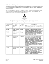
... solder procedures on the PCB. Default operation is in session. The jumper positions are designed to intercom operation. Garmin is not responsible for damage caused during adjustment of these positions, internal sidetone will be heard during transmission. Component R0303... size. Default operation is not capable of phone detection. If this function already. If a jumper is supplied in the installation. B GMA 240 Installation Manual 190-00917-01 If a jumper is usually not disruptive. This should only be performed by alert audio. 2.3.1 Internal Configuration...
... solder procedures on the PCB. Default operation is in session. The jumper positions are designed to intercom operation. Garmin is not responsible for damage caused during adjustment of these positions, internal sidetone will be heard during transmission. Component R0303... size. Default operation is not capable of phone detection. If this function already. If a jumper is supplied in the installation. B GMA 240 Installation Manual 190-00917-01 If a jumper is usually not disruptive. This should only be performed by alert audio. 2.3.1 Internal Configuration...
Installation Manual
Page 15
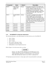
... Configuration Adjustments The following adjustments can be heard when the corresponding ICS KEY for the location of the GMA 240: 1. MASQ (Master Avionics SQuelch) mute level Refer to Figure 2-1 for the MIC position is pressed. GMA 240 Installation Manual 190-00917-01 Page 2-3 Rev. Alert 1 Volume 2. Damage to the unit may occur if an adjustment tool...
... Configuration Adjustments The following adjustments can be heard when the corresponding ICS KEY for the location of the GMA 240: 1. MASQ (Master Avionics SQuelch) mute level Refer to Figure 2-1 for the MIC position is pressed. GMA 240 Installation Manual 190-00917-01 Page 2-3 Rev. Alert 1 Volume 2. Damage to the unit may occur if an adjustment tool...
Installation Manual
Page 16
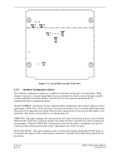
... option is desired during PILOT ISO mode (or by externally wiring pins to chassis through a suitable switch mounted in parallel with the pilot headset output. B GMA 240 Installation Manual 190-00917-01 Microphones are available by the pilot and copilot if crew isolate mode is not squelched. Access Hole Location (Top View) 2.3.3 Hardwire Configuration...
... option is desired during PILOT ISO mode (or by externally wiring pins to chassis through a suitable switch mounted in parallel with the pilot headset output. B GMA 240 Installation Manual 190-00917-01 Microphones are available by the pilot and copilot if crew isolate mode is not squelched. Access Hole Location (Top View) 2.3.3 Hardwire Configuration...
Installation Manual
Page 17
Single-point grounding cannot be isolated from other equipment. Good aircraft electrical/charging system ground bonding is detected. GMA 240 Installation Manual 190-00917-01 Page 2-5 Rev. BUTTON PRESS TONE ENABLE: This input enables an audible tone to be heard when a button ..., EL displays, CRTs, etc). Terminating audio shields just at an audio panel signal input. The wiring diagrams and accompanying notes in this manual should be overstressed for the various avionics producing and processing audio signals. Single-point, in this context, means that the various pieces of ...
Single-point grounding cannot be isolated from other equipment. Good aircraft electrical/charging system ground bonding is detected. GMA 240 Installation Manual 190-00917-01 Page 2-5 Rev. BUTTON PRESS TONE ENABLE: This input enables an audible tone to be heard when a button ..., EL displays, CRTs, etc). Terminating audio shields just at an audio panel signal input. The wiring diagrams and accompanying notes in this manual should be overstressed for the various avionics producing and processing audio signals. Single-point, in this context, means that the various pieces of ...

Installation Manual
Page 18
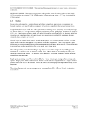
The GMA 240 is recommended to minimize radiated EMI and provide protection from High-Intensity Radiation Fields (HIRF). NOTE Rear support is mounted using a GMA 340 unit rack. GMA 340 Unit Rack (115-00262-00) Page 2-6 Rev. B GMA 240 Installation Manual 190-00917-01 Figure 2-2 shows the GMA 340 unit rack. Figure 2-2. See Section 3.4 for installation instructions. 2.5 GMA 240 Mounting The GMA 240 mounting surface must be capable of providing structural support and electrical bond to the aircraft to ensure a sturdy mount.
The GMA 240 is recommended to minimize radiated EMI and provide protection from High-Intensity Radiation Fields (HIRF). NOTE Rear support is mounted using a GMA 340 unit rack. GMA 340 Unit Rack (115-00262-00) Page 2-6 Rev. B GMA 240 Installation Manual 190-00917-01 Figure 2-2 shows the GMA 340 unit rack. Figure 2-2. See Section 3.4 for installation instructions. 2.5 GMA 240 Mounting The GMA 240 mounting surface must be capable of providing structural support and electrical bond to the aircraft to ensure a sturdy mount.
Installation Manual
Page 19
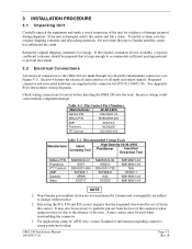
...requires that is damaged, notify the carrier and file a claim. 3 INSTALLATION PROCEDURE 3.1 Unpacking Unit Carefully unpack the equipment and make a visual inspection of the unit for errors before inserting the GMA 240 into the rack. Section 4 defines the electrical characteristics of the wire...off from the face of damage incurred during shipment. Table 3-1. Non-Garmin part numbers shown are not maintained by Garmin and consequently are supplied in the connector kit (P/N 011-00652-00). GMA 240 Installation Manual 190-00917-01 Page 3-1 Rev. It may also be used ...
...requires that is damaged, notify the carrier and file a claim. 3 INSTALLATION PROCEDURE 3.1 Unpacking Unit Carefully unpack the equipment and make a visual inspection of the unit for errors before inserting the GMA 240 into the rack. Section 4 defines the electrical characteristics of the wire...off from the face of damage incurred during shipment. Table 3-1. Non-Garmin part numbers shown are not maintained by Garmin and consequently are supplied in the connector kit (P/N 011-00652-00). GMA 240 Installation Manual 190-00917-01 Page 3-1 Rev. It may also be used ...

Installation Manual
Page 20
... configurations available. CAUTION Do not use excessive force when inserting the GMA 240 into the rack until the unit is felt during installation, stop, and remove the GMA 240 and identify the source of resistance. 5. If heavy resistance is secured in the rack. B GMA 240 Installation Manual 190-00917-01 Turn the Allen wrench clockwise until the jackscrew makes...
... configurations available. CAUTION Do not use excessive force when inserting the GMA 240 into the rack until the unit is felt during installation, stop, and remove the GMA 240 and identify the source of resistance. 5. If heavy resistance is secured in the rack. B GMA 240 Installation Manual 190-00917-01 Turn the Allen wrench clockwise until the jackscrew makes...

