Installation Manual
Page 5
...A-1 GMA 240 Outline Drawing ...A-1 A-2 GMA 240 Connector/Rack Assembly Drawing A-3 A-3 GMA 240 Recommended Panel Cutout Dimensions A-5 B-1 GMA 240 Interconnect Drawing (page 1 of 3 B-1 B-1 GMA 240 Interconnect Drawing (page 2 of 3 B-3 B-1 GMA 240 Interconnect Drawing (page 3 of 3 B-5 B-2 GMA 240, J2401 & J2402 Connector Layout Drawing B-7 C-1 GMA 240 Internal Configuration Jumper Layout Drawing C-1 LIST OF TABLES TABLE PAGE 3-1 Pin Contact Part Numbers...3-1 3-2 Recommended Crimp Tools ...3-1 4-1 J2401 Pin Assignments ...4-2 4-2 J2402 Pin Assignments ...4-3 GMA 240 Installation...
...A-1 GMA 240 Outline Drawing ...A-1 A-2 GMA 240 Connector/Rack Assembly Drawing A-3 A-3 GMA 240 Recommended Panel Cutout Dimensions A-5 B-1 GMA 240 Interconnect Drawing (page 1 of 3 B-1 B-1 GMA 240 Interconnect Drawing (page 2 of 3 B-3 B-1 GMA 240 Interconnect Drawing (page 3 of 3 B-5 B-2 GMA 240, J2401 & J2402 Connector Layout Drawing B-7 C-1 GMA 240 Internal Configuration Jumper Layout Drawing C-1 LIST OF TABLES TABLE PAGE 3-1 Pin Contact Part Numbers...3-1 3-2 Recommended Crimp Tools ...3-1 4-1 J2401 Pin Assignments ...4-2 4-2 J2402 Pin Assignments ...4-3 GMA 240 Installation...

Installation Manual
Page 6
... their Garmin-provided user name and password. MOD LEVEL SERVICE BULLETIN NUMBER SERVICE BULLETIN DATE PURPOSE OF MODIFICATION Page iv Revision B GMA 240 Installation Manual 190-00917-01 The table is current at the time of publication of the modification. GMA 240 HARDWARE MOD LEVEL HISTORY The following table identifies hardware modification (Mod) Levels for the GMA 240 Audio Panel...
... their Garmin-provided user name and password. MOD LEVEL SERVICE BULLETIN NUMBER SERVICE BULLETIN DATE PURPOSE OF MODIFICATION Page iv Revision B GMA 240 Installation Manual 190-00917-01 The table is current at the time of publication of the modification. GMA 240 HARDWARE MOD LEVEL HISTORY The following table identifies hardware modification (Mod) Levels for the GMA 240 Audio Panel...

Installation Manual
Page 7
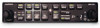
...and microphone directly to a level appropriate for the Garmin GMA 240 Audio Panel. One hundred percent solid state circuitry and extensive use of aircraft owners and operators who require reliability and versatility in the GMA 240 Maintenance Manual, P/N 190-00917-02. Information pertaining ... COM1 and a fail-safe warning audio input in the GMA 240 Pilot's Guide, P/N 190-00917-00. 1.2 Equipment Description The Garmin GMA 240 Audio Panel is not a TSO-certified product and has received no FAA approval or endorsement. GMA 240 Unit View GMA 240 Installation Manual 190-00917-01 Page 1-1 ...
...and microphone directly to a level appropriate for the Garmin GMA 240 Audio Panel. One hundred percent solid state circuitry and extensive use of aircraft owners and operators who require reliability and versatility in the GMA 240 Maintenance Manual, P/N 190-00917-02. Information pertaining ... COM1 and a fail-safe warning audio input in the GMA 240 Pilot's Guide, P/N 190-00917-00. 1.2 Equipment Description The Garmin GMA 240 Audio Panel is not a TSO-certified product and has received no FAA approval or endorsement. GMA 240 Unit View GMA 240 Installation Manual 190-00917-01 Page 1-1 ...
Installation Manual
Page 8
... warning audio input • Full duplex Telephone interface • Front Panel Mini-Jack (MP3 player, cellular phone, etc.) 1.3 Technical Specifications 1.3.1 Physical Characteristics Characteristic Bezel Height Bezel Width Rack Height (Dimple to Dimple) Rack Width Depth Behind Panel with Connectors (measured from face of aircraft panel to rear of connector backshells) GMA 240 Weight (Unit Only) GMA 240 Weight (Installed...
... warning audio input • Full duplex Telephone interface • Front Panel Mini-Jack (MP3 player, cellular phone, etc.) 1.3 Technical Specifications 1.3.1 Physical Characteristics Characteristic Bezel Height Bezel Width Rack Height (Dimple to Dimple) Rack Width Depth Behind Panel with Connectors (measured from face of aircraft panel to rear of connector backshells) GMA 240 Weight (Unit Only) GMA 240 Weight (Installed...
Installation Manual
Page 9
...: 2 (pilot, copilot/passengers) VOX circuits: 4 (one per mic input) Microphone input impedance: 450 Ω (compatible with 150 to +85°C (storage) Altitude 55,000 Feet Audio Panel Functions Dedicated Transceiver inputs: 3 (including TEL) Dedicated Receiver inputs: 4 (all , crew) Telephone interfaces: 1 full-duplex (use LRU pins or front jack) Headphone Outputs Output amplifiers...
...: 2 (pilot, copilot/passengers) VOX circuits: 4 (one per mic input) Microphone input impedance: 450 Ω (compatible with 150 to +85°C (storage) Altitude 55,000 Feet Audio Panel Functions Dedicated Transceiver inputs: 3 (including TEL) Dedicated Receiver inputs: 4 (all , crew) Telephone interfaces: 1 full-duplex (use LRU pins or front jack) Headphone Outputs Output amplifiers...

Installation Manual
Page 13
..., and information pertaining to installation. 2.2 Installation Materials 2.2.1 Equipment Available GMA 240 Audio Panel, Ship Level Assembly, P/N 010-00735-() includes the following sections: • Wiring options - These configuration/adjustments are detailed in the following , depending on part number: Item Connector Kit, GMA 340 Rack Backplate, GMA 340 Unit Assembly, GMA 240 Audio Cables, 2.5 mm RA Stereo Plug Install Rack, GMA 340 Garmin P/N 011-00652-00...
..., and information pertaining to installation. 2.2 Installation Materials 2.2.1 Equipment Available GMA 240 Audio Panel, Ship Level Assembly, P/N 010-00735-() includes the following sections: • Wiring options - These configuration/adjustments are detailed in the following , depending on part number: Item Connector Kit, GMA 340 Rack Backplate, GMA 340 Unit Assembly, GMA 240 Audio Cables, 2.5 mm RA Stereo Plug Install Rack, GMA 340 Garmin P/N 011-00652-00...
Installation Manual
Page 14
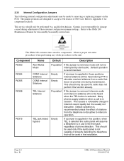
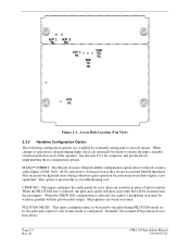
The jumper positions are designed to Appendix C for component location. Garmin is not responsible for disassembly/reassembly instructions. The GMA 240 contains static sensitive components. If this position, when TEL is selected the audio panel will not be made by removing or replacing jumpers on the unit. B GMA 240 Installation Manual 190-00917-01 Refer to accept a 0 Ω resistor...
The jumper positions are designed to Appendix C for component location. Garmin is not responsible for disassembly/reassembly instructions. The GMA 240 contains static sensitive components. If this position, when TEL is selected the audio panel will not be made by removing or replacing jumpers on the unit. B GMA 240 Installation Manual 190-00917-01 Refer to accept a 0 Ω resistor...
Installation Manual
Page 15
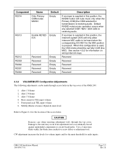
Rear connector TEL input volume 5. Front panel jack TEL input volume 6. Damage to the unit may occur if an adjustment tool is receiving audio. When this configuration is used, the VOX knobs should be made through the top cover. Default RADIO mutes ...will only allow intercom MIC audio to be heard when the corresponding ICS KEY for information on wiring intercom keys. Reserved Reserved Reserved Reserved Reserved 2.3.2 VOLUME/MUTE Configuration Adjustments The following adjustments can be set fully CCW (live MIC). Alert 3 Volume 4. GMA 240 Installation Manual 190-00917-01 ...
Rear connector TEL input volume 5. Front panel jack TEL input volume 6. Damage to the unit may occur if an adjustment tool is receiving audio. When this configuration is used, the VOX knobs should be made through the top cover. Default RADIO mutes ...will only allow intercom MIC audio to be heard when the corresponding ICS KEY for information on wiring intercom keys. Reserved Reserved Reserved Reserved Reserved 2.3.2 VOLUME/MUTE Configuration Adjustments The following adjustments can be set fully CCW (live MIC). Alert 3 Volume 4. GMA 240 Installation Manual 190-00917-01 ...
Installation Manual
Page 16
MASQ™ INHIBIT: The Master Avionics SQuelch inhibit configuration option allows selected avionics audio inputs (COM, NAV, AUX) and alerts to be isolated from these inputs is configured). When the PILOT ISO key is selected, the ...music. Normally, the isolated ICS positions do not exceed the MASQ threshold. B GMA 240 Installation Manual 190-00917-01 When change of operation is desired during flight, these configuration options. CREW ISO: This input configures the audio panel for implementing these can optionally be heard by the pilot during otherwise quiet operation ...
MASQ™ INHIBIT: The Master Avionics SQuelch inhibit configuration option allows selected avionics audio inputs (COM, NAV, AUX) and alerts to be isolated from these inputs is configured). When the PILOT ISO key is selected, the ...music. Normally, the isolated ICS positions do not exceed the MASQ threshold. B GMA 240 Installation Manual 190-00917-01 When change of operation is desired during flight, these configuration options. CREW ISO: This input configures the audio panel for implementing these can optionally be heard by the pilot during otherwise quiet operation ...
Installation Manual
Page 17
... noise. BUTTON PRESS TONE ENABLE: This input enables an audible tone to be overstressed for COM transmit. 2.4 Noise Because the audio panel is also important. GMA 240 Installation Manual 190-00917-01 Page 2-5 Rev. The audio panel may "see" the desired input signal plus an unwanted component injected by magnetic induction when they are brought together, care...
... noise. BUTTON PRESS TONE ENABLE: This input enables an audible tone to be overstressed for COM transmit. 2.4 Noise Because the audio panel is also important. GMA 240 Installation Manual 190-00917-01 Page 2-5 Rev. The audio panel may "see" the desired input signal plus an unwanted component injected by magnetic induction when they are brought together, care...

Installation Manual
Page 21
... to the unit by exercising the installed transceivers, microphone, microphone key, and audio over the pilot headphone's left earpiece. 4. Turn the unit off .] GMA 240 Installation Manual 190-00917-01 Page 3-3 Rev. Check the failsafe operation by rotating the pilot intercom knob fully counter clockwise. 2. Verify that disconnects the audio panel's right channel output from the jack...
... to the unit by exercising the installed transceivers, microphone, microphone key, and audio over the pilot headphone's left earpiece. 4. Turn the unit off .] GMA 240 Installation Manual 190-00917-01 Page 3-3 Rev. Check the failsafe operation by rotating the pilot intercom knob fully counter clockwise. 2. Verify that disconnects the audio panel's right channel output from the jack...

Installation Manual
Page 22
...working properly. 3. Refer to COM 1 and verify that stereo audio is heard when MUSIC 1 is selected as the music source and MUSIC LED is not required. Refer to the GMA 240 Maintenance Manual (Garmin P/N 190-00917-02) as the music source and MUSIC ...GMA 240 Installation Manual 190-00917-01 2. Plug in headsets at each installed avionics unit and check for details. 3.7 CONTINUED AIRWORTHINESS Maintenance of the GMA 240 is on condition" only. Verify that the wiring harness does not touch any moving part. Connect a stereo music source to the front panel jack. Connect a stereo audio...
...working properly. 3. Refer to COM 1 and verify that stereo audio is heard when MUSIC 1 is selected as the music source and MUSIC LED is not required. Refer to the GMA 240 Maintenance Manual (Garmin P/N 190-00917-02) as the music source and MUSIC ...GMA 240 Installation Manual 190-00917-01 2. Plug in headsets at each installed avionics unit and check for details. 3.7 CONTINUED AIRWORTHINESS Maintenance of the GMA 240 is on condition" only. Verify that the wiring harness does not touch any moving part. Connect a stereo music source to the front panel jack. Connect a stereo audio...
Installation Manual
Page 26
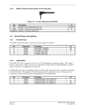
... Connector (front panel 2.5 mm mini-jack) Figure 4-3. 2.5 mm Plug Used with P2403 Pin TIP RING SLEEVE Pin Name MUSIC 1 LEFT IN/TEL MIC OUT HI MUSIC 1 RIGHT IN/TEL AUDIO IN HI MUSIC 1 LO IN/TEL AUDIO LO 4.3 Aircraft Power and Lighting 4.3.1 Aircraft Power The GMA 240 has four inputs... on the front panel and is controlled by a photocell that illuminate each key when selected is controlled by the inputs in the appropriate voltage range) for the backlighting to a supply voltage (in the below table. Pin Connector Pin Name I /O IN/OUT IN -- B GMA 240 Installation Manual 190-00917-...
... Connector (front panel 2.5 mm mini-jack) Figure 4-3. 2.5 mm Plug Used with P2403 Pin TIP RING SLEEVE Pin Name MUSIC 1 LEFT IN/TEL MIC OUT HI MUSIC 1 RIGHT IN/TEL AUDIO IN HI MUSIC 1 LO IN/TEL AUDIO LO 4.3 Aircraft Power and Lighting 4.3.1 Aircraft Power The GMA 240 has four inputs... on the front panel and is controlled by a photocell that illuminate each key when selected is controlled by the inputs in the appropriate voltage range) for the backlighting to a supply voltage (in the below table. Pin Connector Pin Name I /O IN/OUT IN -- B GMA 240 Installation Manual 190-00917-...
Installation Manual
Page 28
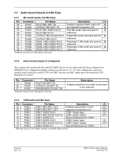
Page 4-6 Rev. B GMA 240 Installation Manual 190-00917-01 Passenger 1 Mic audio and ground IN reference -- Passenger 2 Mic audio and ground IN reference -- 4.5.2 Intercom Key Inputs (if configured) These inputs only perform the described ICS KEY function if the audio panel has been configured for COM 2 * Denotes Active Low (Sinks ...fully CCW (live MIC) because the MIC signal must also break the VOX threshold to be heard in the intercom 4.5.3 COM Audio and Mic Keys Pin Connector Pin Name Description 12 P2401 COM 1 MIC KEY* OUT Enables transmission on the 30 P2401 COM...
Page 4-6 Rev. B GMA 240 Installation Manual 190-00917-01 Passenger 1 Mic audio and ground IN reference -- Passenger 2 Mic audio and ground IN reference -- 4.5.2 Intercom Key Inputs (if configured) These inputs only perform the described ICS KEY function if the audio panel has been configured for COM 2 * Denotes Active Low (Sinks ...fully CCW (live MIC) because the MIC signal must also break the VOX threshold to be heard in the intercom 4.5.3 COM Audio and Mic Keys Pin Connector Pin Name Description 12 P2401 COM 1 MIC KEY* OUT Enables transmission on the 30 P2401 COM...

Pilot's Guide
Page 6
Upon installation, the unit may be pressed to transmit on the aircraft type and the needs of this manual. See the configuration list at the end of the Pilot. A push-to COM 1 and the fail-safe alert audio, such as an autopilot disconnect ...further reduces ambient noise from the avionics inputs. Pushbutton keys control audio selection of COM, NAV, telephone (TEL), and intercom. LED-illuminated key brightness is a headphones only audio control panel. GMA 240 Audio Panel Features and Operation The Garmin GMA 240 is adjusted by photocell dimming. Two AUX inputs are available ...
Upon installation, the unit may be pressed to transmit on the aircraft type and the needs of this manual. See the configuration list at the end of the Pilot. A push-to COM 1 and the fail-safe alert audio, such as an autopilot disconnect ...further reduces ambient noise from the avionics inputs. Pushbutton keys control audio selection of COM, NAV, telephone (TEL), and intercom. LED-illuminated key brightness is a headphones only audio control panel. GMA 240 Audio Panel Features and Operation The Garmin GMA 240 is adjusted by photocell dimming. Two AUX inputs are available ...

