Installation Manual
Page 2
... Telephone: 913.397.8200 Aviation Panel-Mount Technical Support Line (Toll Free) 1.888.606.5482 www.garmin.com Garmin (Europe) Ltd. © Copyright 2010 Garmin Ltd. Liberty House, Bulls Copse Road Hounsdown Business Park Southampton, SO40 9RB U.K. +44/ (0) 870.8501241 Garmin AT, Inc. 2345 Turner...interconnect drawing and added ETSO info C 08/17/10 Added Flight Data Services activation information Page A Revision C DOCUMENT PAGINATION Section Table of this manual may be reproduced, copied, transmitted, disseminated, downloaded or stored in any storage medium, for any revision hereto...
... Telephone: 913.397.8200 Aviation Panel-Mount Technical Support Line (Toll Free) 1.888.606.5482 www.garmin.com Garmin (Europe) Ltd. © Copyright 2010 Garmin Ltd. Liberty House, Bulls Copse Road Hounsdown Business Park Southampton, SO40 9RB U.K. +44/ (0) 870.8501241 Garmin AT, Inc. 2345 Turner...interconnect drawing and added ETSO info C 08/17/10 Added Flight Data Services activation information Page A Revision C DOCUMENT PAGINATION Section Table of this manual may be reproduced, copied, transmitted, disseminated, downloaded or stored in any storage medium, for any revision hereto...
Installation Manual
Page 3
... Table 1-9 Added Flight Data Services activation info GDL 59 Installation Manual 190-00837-00 Page i Revision C This Notice is required to be exported, released, or disclosed to foreign nationals inside or outside of the United States without first obtaining an export license. special handling may not be included on any questions or would like additional information, please refer to our web...
... Table 1-9 Added Flight Data Services activation info GDL 59 Installation Manual 190-00837-00 Page i Revision C This Notice is required to be exported, released, or disclosed to foreign nationals inside or outside of the United States without first obtaining an export license. special handling may not be included on any questions or would like additional information, please refer to our web...

Installation Manual
Page 4
... Cooling Air ...2-2 2.6 Mounting Requirements ...2-2 3. INSTALLATION PROCEDURE 3-1 3.1 Unpacking Unit...3-1 3.2 Wiring Harness Installation ...3-1 3.3 Wi-Fi Antenna Installation ...3-2 3.4 Coaxial Cable Installation...3-4 3.5 Backshell Assembly and Installation 3-5 3.6 Final Installation ...3-5 3.7 Post Installation Configuration and Checkout 3-6 3.8 Activation of Garmin Flight Data Services 3-6 3.9 Continued Airworthiness ...3-6 4. GENERAL DESCRIPTION 1-1 1.1 Introduction...1-1 1.2 Equipment Description ...1-1 1.3 Interface Summary...1-2 1.4 Technical Specifications...
... Cooling Air ...2-2 2.6 Mounting Requirements ...2-2 3. INSTALLATION PROCEDURE 3-1 3.1 Unpacking Unit...3-1 3.2 Wiring Harness Installation ...3-1 3.3 Wi-Fi Antenna Installation ...3-2 3.4 Coaxial Cable Installation...3-4 3.5 Backshell Assembly and Installation 3-5 3.6 Final Installation ...3-5 3.7 Post Installation Configuration and Checkout 3-6 3.8 Activation of Garmin Flight Data Services 3-6 3.9 Continued Airworthiness ...3-6 4. GENERAL DESCRIPTION 1-1 1.1 Introduction...1-1 1.2 Equipment Description ...1-1 1.3 Interface Summary...1-2 1.4 Technical Specifications...

Installation Manual
Page 5
... Drawing (Sheet 2 A-7 B-1 GDL 59 Example Interconnect ...B-1 TABLE LIST OF TABLES PAGE 1-1 Unit with Modular Rack ...1-3 1-2 Unit with Stand-alone Rack...1-4 1-3 Input Voltage ...1-4 1-4 Maximum Current Specifications ...1-4 1-5 General Specifications ...1-4 1-6 Wi-Fi Antenna Minimum Requirements 1-5 1-7 TSO/ETSO Authorizations ...1-6 1-8 TSO/ETSO Deviations ...1-6 1-9 Non-TSO Functions...1-7 1-10 Referenced Publications ...1-7 2-1 Unit Part Number...2-1 2-2 Accessories ...2-1 3-1 Pin Contact Part Numbers...3-1 3-2 Recommended Crimp Tools ...3-1 GDL 59 Installation Manual 190-00837-00...
... Drawing (Sheet 2 A-7 B-1 GDL 59 Example Interconnect ...B-1 TABLE LIST OF TABLES PAGE 1-1 Unit with Modular Rack ...1-3 1-2 Unit with Stand-alone Rack...1-4 1-3 Input Voltage ...1-4 1-4 Maximum Current Specifications ...1-4 1-5 General Specifications ...1-4 1-6 Wi-Fi Antenna Minimum Requirements 1-5 1-7 TSO/ETSO Authorizations ...1-6 1-8 TSO/ETSO Deviations ...1-6 1-9 Non-TSO Functions...1-7 1-10 Referenced Publications ...1-7 2-1 Unit Part Number...2-1 2-2 Accessories ...2-1 3-1 Pin Contact Part Numbers...3-1 3-2 Recommended Crimp Tools ...3-1 GDL 59 Installation Manual 190-00837-00...
Installation Manual
Page 6
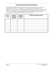
... advisory information on front cover) and is current at www.garmin.com using their Garmin-provided user name and password. MOD LEVEL SERVICE BULLETIN NUMBER SERVICE BULLETIN DATE PURPOSE OF MODIFICATION Page iv Revision C GDL 59 Installation Manual 190-00837-00 GDL 59 HARDWARE MOD LEVEL HISTORY The following table identifies hardware modification (Mod) Levels for the GDL 59. Authorized Garmin Sales and Service Centers are listed with the associated service bulletin number, service bulletin...
... advisory information on front cover) and is current at www.garmin.com using their Garmin-provided user name and password. MOD LEVEL SERVICE BULLETIN NUMBER SERVICE BULLETIN DATE PURPOSE OF MODIFICATION Page iv Revision C GDL 59 Installation Manual 190-00837-00 GDL 59 HARDWARE MOD LEVEL HISTORY The following table identifies hardware modification (Mod) Levels for the GDL 59. Authorized Garmin Sales and Service Centers are listed with the associated service bulletin number, service bulletin...
Installation Manual
Page 7
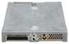
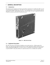
... the Garmin Integrated Flight Deck. GDL 59 Installation Manual 190-00837-00 Page 1-1 Revision C Figure 1-1. GDL 59 Unit View 1.2 Equipment Description The GDL 59 provides a POTS (plain old telephone service) phone interface, a flight parameter data logger, and a high speed data link between the aircraft systems and ground computers while the aircraft is on the ground using the IEEE 802.11g ("Wi-Fi") protocol. 1 GENERAL DESCRIPTION 1.1 Introduction This manual presents mechanical and electrical installation requirements for specific installation instructions in a particular aircraft.
... the Garmin Integrated Flight Deck. GDL 59 Installation Manual 190-00837-00 Page 1-1 Revision C Figure 1-1. GDL 59 Unit View 1.2 Equipment Description The GDL 59 provides a POTS (plain old telephone service) phone interface, a flight parameter data logger, and a high speed data link between the aircraft systems and ground computers while the aircraft is on the ground using the IEEE 802.11g ("Wi-Fi") protocol. 1 GENERAL DESCRIPTION 1.1 Introduction This manual presents mechanical and electrical installation requirements for specific installation instructions in a particular aircraft.
Installation Manual
Page 8
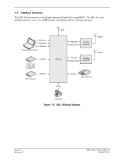
Ethernet Ethernet Ethernet Passenger Computers GDU 1XXX (or GDL 69A or GSD 41) HSDB Other Avionics HSDB WiFi RS-232 Iridium Audio GSR 56 (Optional) GDL 59 RS-232 Iridium Audio GSR 56 (Optional) Iridiu m Iridiu m POTS Audio Audio Panel(s) Hand set Figure 1-2. The GDL 59 can be installed with zero, one, or two GSR 56 units. GDL 59 Block Diagram Page 1-2 Revision C GDL 59 Installation Manual 190-00837-00 Installation will vary between airframes. 1.3 Interface Summary The GDL 59 unit interfaces to the Garmin Integrated Flight Deck using HSDB.
Ethernet Ethernet Ethernet Passenger Computers GDU 1XXX (or GDL 69A or GSD 41) HSDB Other Avionics HSDB WiFi RS-232 Iridium Audio GSR 56 (Optional) GDL 59 RS-232 Iridium Audio GSR 56 (Optional) Iridiu m Iridiu m POTS Audio Audio Panel(s) Hand set Figure 1-2. The GDL 59 can be installed with zero, one, or two GSR 56 units. GDL 59 Block Diagram Page 1-2 Revision C GDL 59 Installation Manual 190-00837-00 Installation will vary between airframes. 1.3 Interface Summary The GDL 59 unit interfaces to the Garmin Integrated Flight Deck using HSDB.
Installation Manual
Page 9
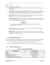
...; Analog POTS Interface: The GDL 59 provides a POTS (plain old telephone service) interface that allows a standard analog telephone to interface to the audio panel(s). • Avionics HSDB: The GDL 59 provides two HSDB ports. Up to two POTS telephones can be used to provide connection to an Electronic Flight Bag (EFB), or for interfacing to the GDL 59. 1.3.1 I/O The GDL 59 supports the following part number: GDL 59 Environmental Qualification Form, Garmin part number 005-00431...
...; Analog POTS Interface: The GDL 59 provides a POTS (plain old telephone service) interface that allows a standard analog telephone to interface to the audio panel(s). • Avionics HSDB: The GDL 59 provides two HSDB ports. Up to two POTS telephones can be used to provide connection to an Electronic Flight Bag (EFB), or for interfacing to the GDL 59. 1.3.1 I/O The GDL 59 supports the following part number: GDL 59 Environmental Qualification Form, Garmin part number 005-00431...

Installation Manual
Page 10
... Specifications Characteristics Operating Temperature Range Humidity Altitude Range Software Compliance Maximum Average Power Input from Antenna Maximum Peak Power (1% Duty Cycle) Input from Antenna Specifications -55 to backup capacitors being charged. Table 1-2. Input Voltage Characteristic Input Voltage Specification 14/28 Vdc See the Environmental Qualification Form for use on surge ratings and minimum/maximum operating voltages. Unit with Stand-alone Rack Characteristic Width Height Depth (Rack w/ Connectors) Unit Weight (GDL 59) Unit (GDL 59) and...
... Specifications Characteristics Operating Temperature Range Humidity Altitude Range Software Compliance Maximum Average Power Input from Antenna Maximum Peak Power (1% Duty Cycle) Input from Antenna Specifications -55 to backup capacitors being charged. Table 1-2. Input Voltage Characteristic Input Voltage Specification 14/28 Vdc See the Environmental Qualification Form for use on surge ratings and minimum/maximum operating voltages. Unit with Stand-alone Rack Characteristic Width Height Depth (Rack w/ Connectors) Unit Weight (GDL 59) Unit (GDL 59) and...
Installation Manual
Page 11
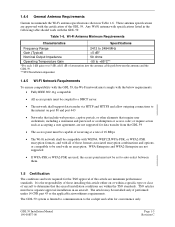
Wi-Fi Antenna Minimum Requirements Characteristics Specifications Frequency Range 2412 to 2484 MHz Gain (Typical) Any Wi-Fi antenna with specifications listed in Table 1-6. These antenna specifications are approved with the GDL 59. Table 1-6. 1.4.4 General Antenna Requirements Garmin recommends the Wi-Fi antenna specifications shown in the following table should work with the certification of the GDL 59.
Wi-Fi Antenna Minimum Requirements Characteristics Specifications Frequency Range 2412 to 2484 MHz Gain (Typical) Any Wi-Fi antenna with specifications listed in Table 1-6. These antenna specifications are approved with the GDL 59. Table 1-6. 1.4.4 General Antenna Requirements Garmin recommends the Wi-Fi antenna specifications shown in the following table should work with the certification of the GDL 59.
Installation Manual
Page 12
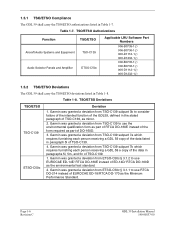
... Software Part Numbers 006-B0735-1( ) 006-B0736-1( ) 006-D1112-1( ) 006-D1232-1( ) 006-B0735-1( ) 006-B0736-1( ) 006-D1112-1( ) 006-D1232-1( ) 1.5.2 TSO/ETSO Deviations The GDL 59 shall carry the TSO/ETSO deviations listed in Table 1-7. Garmin was granted a deviation from TSO-C139 subpart 7a which requires furnishing each person receiving a GDL 59 copy of the data listed in paragraph 5l of TSO-C139. 1. Page 1-6 Revision C GDL 59 Installation Manual...
... Software Part Numbers 006-B0735-1( ) 006-B0736-1( ) 006-D1112-1( ) 006-D1232-1( ) 006-B0735-1( ) 006-B0736-1( ) 006-D1112-1( ) 006-D1232-1( ) 1.5.2 TSO/ETSO Deviations The GDL 59 shall carry the TSO/ETSO deviations listed in Table 1-7. Garmin was granted a deviation from TSO-C139 subpart 7a which requires furnishing each person receiving a GDL 59 copy of the data listed in paragraph 5l of TSO-C139. 1. Page 1-6 Revision C GDL 59 Installation Manual...
Installation Manual
Page 13
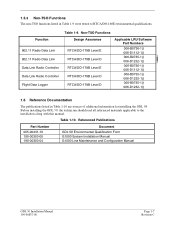
... GDL 59. Referenced Publications Part Number 005-00431-10 190-00303-00 190-00303-04 Document GDL 59 Environmental Qualification Form G1000 System Installation Manual G1000 Line Maintenance and Configuration Manual GDL 59 Installation Manual 190-00837-00 Page 1-7 Revision C Before installing the GDL 59, the technician should read all referenced materials applicable to RTCA/DO-160E environmental qualifications. Function 802.11 Radio Data Link 802.11 Radio Data Link Data Link Radio Controller Data Link Radio Controller Flight Data Logger...
... GDL 59. Referenced Publications Part Number 005-00431-10 190-00303-00 190-00303-04 Document GDL 59 Environmental Qualification Form G1000 System Installation Manual G1000 Line Maintenance and Configuration Manual GDL 59 Installation Manual 190-00837-00 Page 1-7 Revision C Before installing the GDL 59, the technician should read all referenced materials applicable to RTCA/DO-160E environmental qualifications. Function 802.11 Radio Data Link 802.11 Radio Data Link Data Link Radio Controller Data Link Radio Controller Flight Data Logger...

Installation Manual
Page 14
...of the numbers shown below. Garmin will be made at one of incidental or consequential damages, so the above limitations may not apply to repair or replace the unit or software or offer a full refund of purchase. Garmin International, Inc...Garmin Customer Service at no charge to the customer for parts or labor, provided that fail in materials or workmanship for any package purchased through online auctions are not accepted for rebates or other special offers from defects in normal use. Phone: 913/397.8200 FAX: 913/397.0836 Garmin (Europe) Ltd. THIS WARRANTY GIVES YOU SPECIFIC...
...of the numbers shown below. Garmin will be made at one of incidental or consequential damages, so the above limitations may not apply to repair or replace the unit or software or offer a full refund of purchase. Garmin International, Inc...Garmin Customer Service at no charge to the customer for parts or labor, provided that fail in materials or workmanship for any package purchased through online auctions are not accepted for rebates or other special offers from defects in normal use. Phone: 913/397.8200 FAX: 913/397.0836 Garmin (Europe) Ltd. THIS WARRANTY GIVES YOU SPECIFIC...

Installation Manual
Page 15
..., or #20 may be needed for power connections. This minimizes the risk of FAA advisory circulars AC 43.13-1B and AC 43.13-2A, where applicable, may be found useful for the GDL 59. Installation of the following part number: Table 2-1. GDL 59 Installation Manual 190-00837-00 Page 2-1 Revision C 2 INSTALLATION 2.1 Introduction This section provides hardware equipment information for all connections unless otherwise specified by the...
..., or #20 may be needed for power connections. This minimizes the risk of FAA advisory circulars AC 43.13-1B and AC 43.13-2A, where applicable, may be found useful for the GDL 59. Installation of the following part number: Table 2-1. GDL 59 Installation Manual 190-00837-00 Page 2-1 Revision C 2 INSTALLATION 2.1 Introduction This section provides hardware equipment information for all connections unless otherwise specified by the...

Installation Manual
Page 18
... the connector when using 16 AWG wire, contact Garmin for the GDL 59, these factors are several critical factors to push the pin out from the contact. Minimum antenna requirements are subject to the absence of the Wi-Fi antenna, follow the manufacturer's instructions and the instructions in the following sections. 3.3.1 Antenna Mounting For installation mounting of the wire. For applications using an extractor due to change without notice. 2. Non-Garmin part numbers...
... the connector when using 16 AWG wire, contact Garmin for the GDL 59, these factors are several critical factors to push the pin out from the contact. Minimum antenna requirements are subject to the absence of the Wi-Fi antenna, follow the manufacturer's instructions and the instructions in the following sections. 3.3.1 Antenna Mounting For installation mounting of the wire. For applications using an extractor due to change without notice. 2. Non-Garmin part numbers...

Installation Manual
Page 19
... the antenna and the GDL 59 RF input. (4) Antenna input cannot exceed Maximum Power Input levels listed in the aircraft. • 5 inches from a VHF active antenna such as COM or ACARS. • 5 inches from an active radar altimeter (4 GHz). • 12 inches from a UHF/Microwave transmitting antenna such as a transponder, DME, active TCAS, UAT, SATCOM, or Flitephone. 3.3.4 Wi-Fi Antenna to Receiver Signal Requirements Observe the following during the antenna installation: 1. Maintain...
... the antenna and the GDL 59 RF input. (4) Antenna input cannot exceed Maximum Power Input levels listed in the aircraft. • 5 inches from a VHF active antenna such as COM or ACARS. • 5 inches from an active radar altimeter (4 GHz). • 12 inches from a UHF/Microwave transmitting antenna such as a transponder, DME, active TCAS, UAT, SATCOM, or Flitephone. 3.3.4 Wi-Fi Antenna to Receiver Signal Requirements Observe the following during the antenna installation: 1. Maintain...

Installation Manual
Page 21
... rear plate using the provided nutplates. 4. This may cause damage to occur to ensure the rear plate is felt during installation, stop! Lock the GDL 59 in Section 3.5. 2. Remove the GDL 59 and identify the source of torque exceeding 14 in the connector kit. 3. The application of resistance. Connect both connectors to this manual. 1. To assemble the backshell refer to instructions provided in...
... rear plate using the provided nutplates. 4. This may cause damage to occur to ensure the rear plate is felt during installation, stop! Lock the GDL 59 in Section 3.5. 2. Remove the GDL 59 and identify the source of torque exceeding 14 in the connector kit. 3. The application of resistance. Connect both connectors to this manual. 1. To assemble the backshell refer to instructions provided in...

Installation Manual
Page 22
... to activate the GDL 59 for Garmin Flight Data Services, please contact Garmin Product Support at one of the following information ready prior to approved aircraft maintenance manuals or manual supplements for a specific aircraft and are completed. GDL 59 settings are predetermined for actual aircraft maintenance requirements. Central USA): • 1.866.739.5687 (toll free in aircraft o G1000 system ID number o Name of aircraft owner and contact information o Credit card information 3.9 Continued Airworthiness Maintenance of the GDL 59 is loaded to the installer configuring the...
... to activate the GDL 59 for Garmin Flight Data Services, please contact Garmin Product Support at one of the following information ready prior to approved aircraft maintenance manuals or manual supplements for a specific aircraft and are completed. GDL 59 settings are predetermined for actual aircraft maintenance requirements. Central USA): • 1.866.739.5687 (toll free in aircraft o G1000 system ID number o Name of aircraft owner and contact information o Credit card information 3.9 Continued Airworthiness Maintenance of the GDL 59 is loaded to the installer configuring the...

Installation Manual
Page 26
... 20 mA max Pin Name IRIDIUM 1 REMOTE POWER ON* IRIDIUM 2 REMOTE POWER ON* • Denotes Active Low (Ground to activate) Connector Pin I /O P591 10 In P591 30 In P591 9 Out P591 29 Out P591 4 In P591 24 In P591 3 Out P591 23 Out Page 4-4 Revision C GDL 59 Installation Manual 190-00837-00 4.3.2 Remote Power On These outputs are used in the Garmin Integrated Flight Deck system. DISCRETE OUT* pins: INACTIVE: Floating...
... 20 mA max Pin Name IRIDIUM 1 REMOTE POWER ON* IRIDIUM 2 REMOTE POWER ON* • Denotes Active Low (Ground to activate) Connector Pin I /O P591 10 In P591 30 In P591 9 Out P591 29 Out P591 4 In P591 24 In P591 3 Out P591 23 Out Page 4-4 Revision C GDL 59 Installation Manual 190-00837-00 4.3.2 Remote Power On These outputs are used in the Garmin Integrated Flight Deck system. DISCRETE OUT* pins: INACTIVE: Floating...

Installation Manual
Page 27
... Out 4.4.3 RS-232 Serial Input/Output The RS-232 outputs conform to be used for communication with an output voltage swing of IEEE standard 802.3 for other functions in the future. 4.4.2 User Ethernet The GDL 59 has three Ethernet data busses that meet the hardware aspects of at least ±5 V when driving a standard RS-232 load. NOTE Garmin recommends leaving USER ETHERNET 3 unconnected, as...
... Out 4.4.3 RS-232 Serial Input/Output The RS-232 outputs conform to be used for communication with an output voltage swing of IEEE standard 802.3 for other functions in the future. 4.4.2 User Ethernet The GDL 59 has three Ethernet data busses that meet the hardware aspects of at least ±5 V when driving a standard RS-232 load. NOTE Garmin recommends leaving USER ETHERNET 3 unconnected, as...

