

Maintenance Manual
Page 1
GAD 42 MAINTENANCE MANUAL GARMIN International, Inc. 1200 E. 151st Street Olathe, KS 66062 USA 190-00159-01, Revision A July 2001
GAD 42 MAINTENANCE MANUAL GARMIN International, Inc. 1200 E. 151st Street Olathe, KS 66062 USA 190-00159-01, Revision A July 2001
Maintenance Manual
Page 2
... must contain the complete text of this copyright notice and provided further that any unauthorized commercial distribution of GARMIN Corporation. Insertion Date By GAD 42 MAINTENANCE MANUAL P/N 190-00159-01 Page 1 Rev. © Copyright 2001 GARMIN Corporation All Rights Reserved Except as expressly provided below, no part of this manual may be viewed and...
... must contain the complete text of this copyright notice and provided further that any unauthorized commercial distribution of GARMIN Corporation. Insertion Date By GAD 42 MAINTENANCE MANUAL P/N 190-00159-01 Page 1 Rev. © Copyright 2001 GARMIN Corporation All Rights Reserved Except as expressly provided below, no part of this manual may be viewed and...
Maintenance Manual
Page 3
... CFR, Chapter VII, Subchapter C) and which may be exported, released, or disclosed to $1,000,000 under Section 2410 of the Export Administration Act of 1979. A GAD 42 MAINTENANCE MANUAL P/N 190-00159-01 Page 2 Rev. Include this notice with any reproduced portion of this document.
... CFR, Chapter VII, Subchapter C) and which may be exported, released, or disclosed to $1,000,000 under Section 2410 of the Export Administration Act of 1979. A GAD 42 MAINTENANCE MANUAL P/N 190-00159-01 Page 2 Rev. Include this notice with any reproduced portion of this document.
Maintenance Manual
Page 4
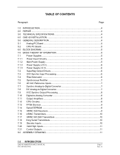
A TABLE OF CONTENTS Paragraph Page 1.0 INTRODUCTION ...4 2.0 REPAIR ...4 3.0 TECHNICAL SPECIFICATIONS 4 4.0 GAD 42 INSTALLATION 4 5.0 GENERAL DESCRIPTION 4 5.1 Analog PC Board 4 5.2 CPU PC Board 5 6.0 BLOCK DIAGRAM 5 7.0 BASIC THEORY OF OPERATION 5 7.1 Power Supplies 5 7.1.1 Power Input Circuitry 5 7.1.2 Main Power Supply 5 7.1.3 Power Supply (+5 V ...10 7.18 King Serial Transmitters 10 7.19 Discrete Inputs 10 7.20 Valid High Inputs 11 7.21 Control Outputs 11 8.0 ASSEMBLY DRAWING 11 1.0 INTRODUCTION GAD 42 MAINTENANCE MANUAL P/N 190-00159-01 Page 3 Rev.
A TABLE OF CONTENTS Paragraph Page 1.0 INTRODUCTION ...4 2.0 REPAIR ...4 3.0 TECHNICAL SPECIFICATIONS 4 4.0 GAD 42 INSTALLATION 4 5.0 GENERAL DESCRIPTION 4 5.1 Analog PC Board 4 5.2 CPU PC Board 5 6.0 BLOCK DIAGRAM 5 7.0 BASIC THEORY OF OPERATION 5 7.1 Power Supplies 5 7.1.1 Power Input Circuitry 5 7.1.2 Main Power Supply 5 7.1.3 Power Supply (+5 V ...10 7.18 King Serial Transmitters 10 7.19 Discrete Inputs 10 7.20 Valid High Inputs 11 7.21 Control Outputs 11 8.0 ASSEMBLY DRAWING 11 1.0 INTRODUCTION GAD 42 MAINTENANCE MANUAL P/N 190-00159-01 Page 3 Rev.

Maintenance Manual
Page 5
... systems to be sent as 429 data • Input analog true airspeed to Garmin long-range navigation products. Return faulty units to GARMIN for service. 3.0 TECHNICAL SPECIFICATIONS Technical specifications for the GAD 42 are listed in the GAD 42 Installation Manual, P/N 190-00159-00. 4.0 GAD 42 INSTALLATION Installation information for the unit is a microprocessor based input/output (I /O circuitry...
... systems to be sent as 429 data • Input analog true airspeed to Garmin long-range navigation products. Return faulty units to GARMIN for service. 3.0 TECHNICAL SPECIFICATIONS Technical specifications for the GAD 42 are listed in the GAD 42 Installation Manual, P/N 190-00159-00. 4.0 GAD 42 INSTALLATION Installation information for the unit is a microprocessor based input/output (I /O circuitry...
Maintenance Manual
Page 6
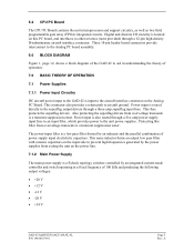
...understanding the theory of operation. 7.0 BASIC THEORY OF OPERATION 7.1 Power Supplies 7.1.1 Power Input Circuitry DC aircraft power input to the GAD 42 is input to the superflag output drivers through a 62-pin high-density D-subminiature aircraft interface connector. This connector also provides a... kHz and producing the following output voltages: • +20 V • +12 V • -12 V • -20 V • +34 V GAD 42 MAINTENANCE MANUAL P/N 190-00159-01 Page 5 Rev. A Protecting this PC board, and interfaces to the unit power supplies. Power input is also routed through a five...
...understanding the theory of operation. 7.0 BASIC THEORY OF OPERATION 7.1 Power Supplies 7.1.1 Power Input Circuitry DC aircraft power input to the GAD 42 is input to the superflag output drivers through a 62-pin high-density D-subminiature aircraft interface connector. This connector also provides a... kHz and producing the following output voltages: • +20 V • +12 V • -12 V • -20 V • +34 V GAD 42 MAINTENANCE MANUAL P/N 190-00159-01 Page 5 Rev. A Protecting this PC board, and interfaces to the unit power supplies. Power input is also routed through a five...
Maintenance Manual
Page 7
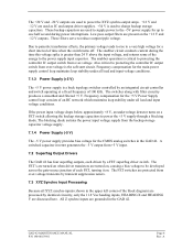
...V are used as IC and output driver supplies. +34 V is the soft start circuit. Frequency compensation for the CMOS analog switches in the GAD 42. A switched capacitor inverter generates the -5 V output from the backup storage capacitor voltage supply. 7.1.4 Power Supply (-5 V) The -5 V power ... parasitic transformer effects, the primary voltage tends to rise to charge backup storage capacitors. The FET switches are grounded in the GAD 42. Also critical to protecting the controller IC output switch from over -voltage. A Frequency compensation for a short interval of an...
...V are used as IC and output driver supplies. +34 V is the soft start circuit. Frequency compensation for the CMOS analog switches in the GAD 42. A switched capacitor inverter generates the -5 V output from the backup storage capacitor voltage supply. 7.1.4 Power Supply (-5 V) The -5 V power ... parasitic transformer effects, the primary voltage tends to rise to charge backup storage capacitors. The FET switches are grounded in the GAD 42. Also critical to protecting the controller IC output switch from over -voltage. A Frequency compensation for a short interval of an...
Maintenance Manual
Page 8
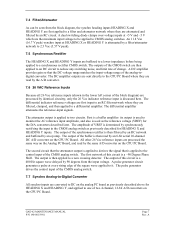
... the CMOS switch are filtered, clamped, and then applied to a differential amplifier. The differential amplifier attenuates the reference-input signals. The first network of change. GAD 42 MAINTENANCE MANUAL P/N 190-00159-01 Page 7 Rev. 7.4 Filter/Attenuator As can be applied to derives the signal that the DC voltage range matches the input...
... the CMOS switch are filtered, clamped, and then applied to a differential amplifier. The differential amplifier attenuates the reference-input signals. The first network of change. GAD 42 MAINTENANCE MANUAL P/N 190-00159-01 Page 7 Rev. 7.4 Filter/Attenuator As can be applied to derives the signal that the DC voltage range matches the input...
Maintenance Manual
Page 9
...The output amps use a unity-gain buffer amp, a high-voltage op-amp, and inverting push-pull Darlington driver transistors all DC voltage monitoring in the GAD 42. 7.10 Digital-to 5 V range required by identical circuitry, only the SELECTED CRS DRIVE X/COS and SELECTED CRS DRIVE Y/SIN outputs will be transmitted to... are protected from negative or over -voltage transients by the ratio of two resistors. This element is possible due to the VREF input. GAD 42 MAINTENANCE MANUAL P/N 190-00159-01 Page 8 Rev. The amplitude is a scaled version of the block diagram) are grounded in the...
...The output amps use a unity-gain buffer amp, a high-voltage op-amp, and inverting push-pull Darlington driver transistors all DC voltage monitoring in the GAD 42. 7.10 Digital-to 5 V range required by identical circuitry, only the SELECTED CRS DRIVE X/COS and SELECTED CRS DRIVE Y/SIN outputs will be transmitted to... are protected from negative or over -voltage transients by the ratio of two resistors. This element is possible due to the VREF input. GAD 42 MAINTENANCE MANUAL P/N 190-00159-01 Page 8 Rev. The amplitude is a scaled version of the block diagram) are grounded in the...
Maintenance Manual
Page 10
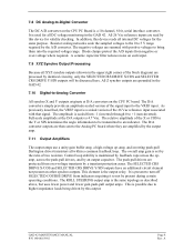
...for RS-232 format input and output. If A is low, and B is too low, and if the micromonitor latched output fails to FPGA "B" input. GAD 42 MAINTENANCE MANUAL P/N 190-00159-01 Page 9 Rev. A flash memory device contains unit software code, and can then pass data. A Static Ram device provides storage... that is in flash memory. A If the devices are received and transmit directly from the CPU are programmed by RS-232 interface when the GAD 42 is configured on a PNP output transistor. The serial data bus to the EEPROM is high, current flows in a serial EEPROM IC on the...
...for RS-232 format input and output. If A is low, and B is too low, and if the micromonitor latched output fails to FPGA "B" input. GAD 42 MAINTENANCE MANUAL P/N 190-00159-01 Page 9 Rev. A flash memory device contains unit software code, and can then pass data. A Static Ram device provides storage... that is in flash memory. A If the devices are received and transmit directly from the CPU are programmed by RS-232 interface when the GAD 42 is configured on a PNP output transistor. The serial data bus to the EEPROM is high, current flows in a serial EEPROM IC on the...

Maintenance Manual
Page 11
... two exceptions: Gain is set of data bits, the FPGA data output is diode-isolated from the bus such that are within their feedback loops. GAD 42 MAINTENANCE MANUAL P/N 190-00159-01 Page 10 Rev.
... two exceptions: Gain is set of data bits, the FPGA data output is diode-isolated from the bus such that are within their feedback loops. GAD 42 MAINTENANCE MANUAL P/N 190-00159-01 Page 10 Rev.
Maintenance Manual
Page 12
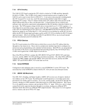
... Outputs All control outputs are located on the CPU board, and are identical to the output described here. A diode provides transient voltage protection for the GAD 42. If the current through a resistor is turned off for over 10 V, a diode conducts base current to a transistor through a resistor to ground, turning it off . 7.20... data bus through a resistor. This shorts the gate voltage applied to the FET to a power FET. When the HDG_VALID_HI input pin is applied through a resistor. GAD 42 MAINTENANCE MANUAL P/N 190-00159-01 Page 11 Rev.
... Outputs All control outputs are located on the CPU board, and are identical to the output described here. A diode provides transient voltage protection for the GAD 42. If the current through a resistor is turned off for over 10 V, a diode conducts base current to a transistor through a resistor to ground, turning it off . 7.20... data bus through a resistor. This shorts the gate voltage applied to the FET to a power FET. When the HDG_VALID_HI input pin is applied through a resistor. GAD 42 MAINTENANCE MANUAL P/N 190-00159-01 Page 11 Rev.
Maintenance Manual
Page 13
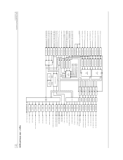
A GAD 42 Block Diagram Page 12 Rev. HEADING X HEADING Y REMOTE CRS SELECT X/COS REMOTE CRS SELECT Y/SIN TRUE AIRSPEED X/SIGNAL TRUE AIRSPEED Y/REFERENCE RESERVED (SPARE X IN) RESERVED (... ARINC 561/568 DATA ARINC 561/568 SYNC DRIVER LEVEL SHIFT ARINC 561/568 CONTINUOUS CLOCK KING SERIAL DATA KING SERIAL CLOCK KING SERIAL SYNC GAD 42 MAINTENANCE MANUAL P/N 190-00159-01 Figure 1.
A GAD 42 Block Diagram Page 12 Rev. HEADING X HEADING Y REMOTE CRS SELECT X/COS REMOTE CRS SELECT Y/SIN TRUE AIRSPEED X/SIGNAL TRUE AIRSPEED Y/REFERENCE RESERVED (SPARE X IN) RESERVED (... ARINC 561/568 DATA ARINC 561/568 SYNC DRIVER LEVEL SHIFT ARINC 561/568 CONTINUOUS CLOCK KING SERIAL DATA KING SERIAL CLOCK KING SERIAL SYNC GAD 42 MAINTENANCE MANUAL P/N 190-00159-01 Figure 1.
Maintenance Manual
Page 14
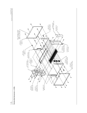
...-00 (2 PLCS) END PLATE 115-00265-00 SIDE EXTRUSION 135-00007-01 (2 PLCS) INSULATOR COVER 250-00064-00 (2 PLCS) BOARD HEADERS 334-00039-00 (3 PLCS) GAD 42 MAINTENANCE MANUAL P/N 190-00159-01 COVER 115-00266-00 INSULATOR COVER (2 PLCS) 250-00064-00 (REF) INSIDE SURFACE ONLY SCREW 211-632340-06 (4 PLCS) ANALOG...
...-00 (2 PLCS) END PLATE 115-00265-00 SIDE EXTRUSION 135-00007-01 (2 PLCS) INSULATOR COVER 250-00064-00 (2 PLCS) BOARD HEADERS 334-00039-00 (3 PLCS) GAD 42 MAINTENANCE MANUAL P/N 190-00159-01 COVER 115-00266-00 INSULATOR COVER (2 PLCS) 250-00064-00 (REF) INSIDE SURFACE ONLY SCREW 211-632340-06 (4 PLCS) ANALOG...

