
Maintenance Manual
Page 1
GAD 42 MAINTENANCE MANUAL GARMIN International, Inc. 1200 E. 151st Street Olathe, KS 66062 USA 190-00159-01, Revision A July 2001
GAD 42 MAINTENANCE MANUAL GARMIN International, Inc. 1200 E. 151st Street Olathe, KS 66062 USA 190-00159-01, Revision A July 2001
Maintenance Manual
Page 2
Insertion Date By GAD 42 MAINTENANCE MANUAL P/N 190-00159-01 Page 1 Rev. A © Copyright 2001 GARMIN Corporation All Rights Reserved Except as expressly provided below, no part of this manual may be viewed and to be reproduced, copied, transmitted, disseminated, downloaded or stored in ...of any revision hereto, provided that such electronic or printed copy of this manual or revision must contain the complete text of this manual or any unauthorized commercial distribution of GARMIN Corporation. GARMIN International, Inc. 1200 E. 151st Street Olathe, KS 66062 USA Telephone: 913...
Insertion Date By GAD 42 MAINTENANCE MANUAL P/N 190-00159-01 Page 1 Rev. A © Copyright 2001 GARMIN Corporation All Rights Reserved Except as expressly provided below, no part of this manual may be viewed and to be reproduced, copied, transmitted, disseminated, downloaded or stored in ...of any revision hereto, provided that such electronic or printed copy of this manual or revision must contain the complete text of this manual or any unauthorized commercial distribution of GARMIN Corporation. GARMIN International, Inc. 1200 E. 151st Street Olathe, KS 66062 USA Telephone: 913...
Maintenance Manual
Page 3
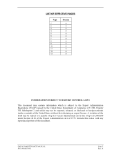
A GAD 42 MAINTENANCE MANUAL P/N 190-00159-01 Page 2 Rev. LIST OF EFFECTIVE PAGES Page 1 2 3 4 5 6 7 8 9 10 11 12 13 Revision A A A A A A A A A A A A A INFORMATION SUBJECT TO EXPORT CONTROL LAWS This document may contain ...
A GAD 42 MAINTENANCE MANUAL P/N 190-00159-01 Page 2 Rev. LIST OF EFFECTIVE PAGES Page 1 2 3 4 5 6 7 8 9 10 11 12 13 Revision A A A A A A A A A A A A A INFORMATION SUBJECT TO EXPORT CONTROL LAWS This document may contain ...
Maintenance Manual
Page 4
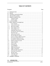
TABLE OF CONTENTS Paragraph Page 1.0 INTRODUCTION ...4 2.0 REPAIR ...4 3.0 TECHNICAL SPECIFICATIONS 4 4.0 GAD 42 INSTALLATION 4 5.0 GENERAL DESCRIPTION 4 5.1 Analog PC Board 4 5.2 CPU PC Board 5 6.0 BLOCK DIAGRAM 5 7.0 BASIC THEORY OF OPERATION 5 7.1 Power Supplies 5 7.1.1 Power Input Circuitry 5 7.1.2 Main Power Supply 5 7.1.3 Power Supply (+5 V... 10 7.18 King Serial Transmitters 10 7.19 Discrete Inputs 10 7.20 Valid High Inputs 11 7.21 Control Outputs 11 8.0 ASSEMBLY DRAWING 11 1.0 INTRODUCTION GAD 42 MAINTENANCE MANUAL P/N 190-00159-01 Page 3 Rev. A
TABLE OF CONTENTS Paragraph Page 1.0 INTRODUCTION ...4 2.0 REPAIR ...4 3.0 TECHNICAL SPECIFICATIONS 4 4.0 GAD 42 INSTALLATION 4 5.0 GENERAL DESCRIPTION 4 5.1 Analog PC Board 4 5.2 CPU PC Board 5 6.0 BLOCK DIAGRAM 5 7.0 BASIC THEORY OF OPERATION 5 7.1 Power Supplies 5 7.1.1 Power Input Circuitry 5 7.1.2 Main Power Supply 5 7.1.3 Power Supply (+5 V... 10 7.18 King Serial Transmitters 10 7.19 Discrete Inputs 10 7.20 Valid High Inputs 11 7.21 Control Outputs 11 8.0 ASSEMBLY DRAWING 11 1.0 INTRODUCTION GAD 42 MAINTENANCE MANUAL P/N 190-00159-01 Page 3 Rev. A

Maintenance Manual
Page 5
... and digital avionics systems to aircraft power and other avionics. A 44-pin high-density D-subminiature aircraft interface connector provides interfaces to Garmin long-range navigation products. GAD 42 MAINTENANCE MANUAL P/N 190-00159-01 Page 4 Rev. A Return faulty units to GARMIN for service. 3.0 TECHNICAL SPECIFICATIONS Technical specifications for the unit is a microprocessor based input/output (I /O circuitry.
... and digital avionics systems to aircraft power and other avionics. A 44-pin high-density D-subminiature aircraft interface connector provides interfaces to Garmin long-range navigation products. GAD 42 MAINTENANCE MANUAL P/N 190-00159-01 Page 4 Rev. A Return faulty units to GARMIN for service. 3.0 TECHNICAL SPECIFICATIONS Technical specifications for the unit is a microprocessor based input/output (I /O circuitry.
Maintenance Manual
Page 6
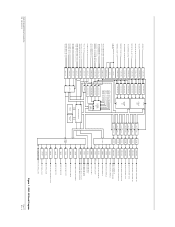
...kHz and producing the following output voltages: • +20 V • +12 V • -12 V • -20 V • +34 V GAD 42 MAINTENANCE MANUAL P/N 190-00159-01 Page 5 Rev. Three 18-pin header board connectors provide interconnect to the Analog PC board assembly. 6.0 BLOCK DIAGRAM Figure 1, page 12, shows... a block diagram of the GAD 42 to aid in understanding the theory of power supply input electrolytic capacitors. ...
...kHz and producing the following output voltages: • +20 V • +12 V • -12 V • -20 V • +34 V GAD 42 MAINTENANCE MANUAL P/N 190-00159-01 Page 5 Rev. Three 18-pin header board connectors provide interconnect to the Analog PC board assembly. 6.0 BLOCK DIAGRAM Figure 1, page 12, shows... a block diagram of the GAD 42 to aid in understanding the theory of power supply input electrolytic capacitors. ...
Maintenance Manual
Page 7
...during power interruptions. These backup capacitors are used to protecting the controller IC output switch from +5 V input. 7.2 Superflag Output Drivers The GAD 42 has four superflag outputs, each FET, turning it on a FET switch allowing the backup storage capacitors to power the +5 V supply through...one half second during the time this voltage spike is the soft start circuit. GAD 42 MAINTENANCE MANUAL P/N 190-00159-01 Page 6 Rev. A Low pass output filters are grounded in the GAD 42. The blocking diode isolates the power input voltage supply from over -voltage is greater...
...during power interruptions. These backup capacitors are used to protecting the controller IC output switch from +5 V input. 7.2 Superflag Output Drivers The GAD 42 has four superflag outputs, each FET, turning it on a FET switch allowing the backup storage capacitors to power the +5 V supply through...one half second during the time this voltage spike is the soft start circuit. GAD 42 MAINTENANCE MANUAL P/N 190-00159-01 Page 6 Rev. A Low pass output filters are grounded in the GAD 42. The blocking diode isolates the power input voltage supply from over -voltage is greater...
Maintenance Manual
Page 8
... that the attenuator output is applied to derives the signal that the DC voltage range matches the input voltage range of the CMOS analog switch. GAD 42 MAINTENANCE MANUAL P/N 190-00159-01 Page 7 Rev. A A dual switching diode clamps over-voltage inputs at HEADING X or HEADING Y is applied to two circuits. The outputs of...
... that the attenuator output is applied to derives the signal that the DC voltage range matches the input voltage range of the CMOS analog switch. GAD 42 MAINTENANCE MANUAL P/N 190-00159-01 Page 7 Rev. A A dual switching diode clamps over-voltage inputs at HEADING X or HEADING Y is applied to two circuits. The outputs of...
Maintenance Manual
Page 9
...STEERING output amp is 4.7 Vac. It is used for the same purpose. All Z synchro outputs are grounded in the GAD 42. 7.10 Digital-to-Analog Converter All synchro X and Y outputs originate at the D/A outputs is the same topology as... impedance loads being driven by this device reads all internal DC voltages for all DC voltage monitoring in the GAD 42. This element is maintained by feedback caps across the opamp, across the push-pull drivers, and by an... associated with positive voltages to bring them into the required voltage range. GAD 42 MAINTENANCE MANUAL P/N 190-00159-01 Page 8 Rev.
...STEERING output amp is 4.7 Vac. It is used for the same purpose. All Z synchro outputs are grounded in the GAD 42. 7.10 Digital-to-Analog Converter All synchro X and Y outputs originate at the D/A outputs is the same topology as... impedance loads being driven by this device reads all internal DC voltages for all DC voltage monitoring in the GAD 42. This element is maintained by feedback caps across the opamp, across the push-pull drivers, and by an... associated with positive voltages to bring them into the required voltage range. GAD 42 MAINTENANCE MANUAL P/N 190-00159-01 Page 8 Rev.
Maintenance Manual
Page 10
...IC address latches latch CPU address data when present on unit power-up by RS-232 interface when the GAD 42 is stored in a serial EEPROM IC on the CPU board. After level shifting, both provide a 12... out to toggle indicating CPU lockup. Both FPGA's are all input to 16 MHz. This causes Vcc to the GAD 42, and is provided by two D flip-flop IC's. The VPP program voltage for output by an 11.8 VDC .../568 and King serial data transmitters. 7.12 CPU Circuitry The GAD 42 CPU board contains the CPU which is in operation. GAD 42 MAINTENANCE MANUAL P/N 190-00159-01 Page 9 Rev.
...IC address latches latch CPU address data when present on unit power-up by RS-232 interface when the GAD 42 is stored in a serial EEPROM IC on the CPU board. After level shifting, both provide a 12... out to toggle indicating CPU lockup. Both FPGA's are all input to 16 MHz. This causes Vcc to the GAD 42, and is provided by two D flip-flop IC's. The VPP program voltage for output by an 11.8 VDC .../568 and King serial data transmitters. 7.12 CPU Circuitry The GAD 42 CPU board contains the CPU which is in operation. GAD 42 MAINTENANCE MANUAL P/N 190-00159-01 Page 9 Rev.

Maintenance Manual
Page 11
... 2.2, and high-frequency attenuation is turned off. King serial data transmission is tri-stated. A capacitor and resistor form a low-pass filter to the output amp. GAD 42 MAINTENANCE MANUAL P/N 190-00159-01 Page 10 Rev. A
... 2.2, and high-frequency attenuation is turned off. King serial data transmission is tri-stated. A capacitor and resistor form a low-pass filter to the output amp. GAD 42 MAINTENANCE MANUAL P/N 190-00159-01 Page 10 Rev. A
Maintenance Manual
Page 12
...base current to a transistor through the resistor exceeds about 0.5 A, enough voltage is turned off. A A diode provides transient voltage protection for the GAD 42. When the HDG_VALID_HI input is open, grounded, or connected to a voltage less than 10 V, no base current can flow, and the transistor... resistor to turn on Q581. This turns the FET on, and DIST_IND_CONTROL is grounded through a resistor is generated by the CPU. GAD 42 MAINTENANCE MANUAL P/N 190-00159-01 Page 11 Rev. This turns on the transistor, and the output normally connected to Vcc through a resistor. ...
...base current to a transistor through the resistor exceeds about 0.5 A, enough voltage is turned off. A A diode provides transient voltage protection for the GAD 42. When the HDG_VALID_HI input is open, grounded, or connected to a voltage less than 10 V, no base current can flow, and the transistor... resistor to turn on Q581. This turns the FET on, and DIST_IND_CONTROL is grounded through a resistor is generated by the CPU. GAD 42 MAINTENANCE MANUAL P/N 190-00159-01 Page 11 Rev. This turns on the transistor, and the output normally connected to Vcc through a resistor. ...
Maintenance Manual
Page 13
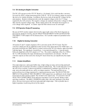
A GAD 42 Block Diagram Page 12 Rev. HEADING X HEADING Y REMOTE CRS SELECT X/COS REMOTE CRS SELECT Y/SIN TRUE AIRSPEED X/SIGNAL TRUE AIRSPEED Y/REFERENCE RESERVED (SPARE X IN) RESERVED (... ARINC 561/568 DATA ARINC 561/568 SYNC DRIVER LEVEL SHIFT ARINC 561/568 CONTINUOUS CLOCK KING SERIAL DATA KING SERIAL CLOCK KING SERIAL SYNC GAD 42 MAINTENANCE MANUAL P/N 190-00159-01 Figure 1.
A GAD 42 Block Diagram Page 12 Rev. HEADING X HEADING Y REMOTE CRS SELECT X/COS REMOTE CRS SELECT Y/SIN TRUE AIRSPEED X/SIGNAL TRUE AIRSPEED Y/REFERENCE RESERVED (SPARE X IN) RESERVED (... ARINC 561/568 DATA ARINC 561/568 SYNC DRIVER LEVEL SHIFT ARINC 561/568 CONTINUOUS CLOCK KING SERIAL DATA KING SERIAL CLOCK KING SERIAL SYNC GAD 42 MAINTENANCE MANUAL P/N 190-00159-01 Figure 1.
Maintenance Manual
Page 14
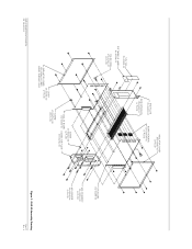
... (2 PLCS) END PLATE 115-00265-00 SIDE EXTRUSION 135-00007-01 (2 PLCS) INSULATOR COVER 250-00064-00 (2 PLCS) BOARD HEADERS 334-00039-00 (3 PLCS) GAD 42 MAINTENANCE MANUAL P/N 190-00159-01 COVER 115-00266-00 INSULATOR COVER (2 PLCS) 250-00064-00 (REF) INSIDE SURFACE ONLY SCREW 211-632340-06 (4 PLCS) ANALOG BOARD 012...
... (2 PLCS) END PLATE 115-00265-00 SIDE EXTRUSION 135-00007-01 (2 PLCS) INSULATOR COVER 250-00064-00 (2 PLCS) BOARD HEADERS 334-00039-00 (3 PLCS) GAD 42 MAINTENANCE MANUAL P/N 190-00159-01 COVER 115-00266-00 INSULATOR COVER (2 PLCS) 250-00064-00 (REF) INSIDE SURFACE ONLY SCREW 211-632340-06 (4 PLCS) ANALOG BOARD 012...


