Maintenance Manual
Page 4
A TABLE OF CONTENTS Paragraph Page 1.0 INTRODUCTION ...4 2.0 REPAIR ...4 3.0 TECHNICAL SPECIFICATIONS 4 4.0 GAD 42 INSTALLATION 4 5.0 GENERAL DESCRIPTION 4 5.1 Analog PC Board 4 5.2 CPU PC Board 5 6.0 BLOCK DIAGRAM 5 7.0 BASIC THEORY OF OPERATION 5 7.1 Power Supplies 5 7.1.1 Power Input Circuitry 5 7.1.2 Main Power Supply 5 7.1.3 Power Supply (+5 V 6... 7.18 King Serial Transmitters 10 7.19 Discrete Inputs 10 7.20 Valid High Inputs 11 7.21 Control Outputs 11 8.0 ASSEMBLY DRAWING 11 1.0 INTRODUCTION GAD 42 MAINTENANCE MANUAL P/N 190-00159-01 Page 3 Rev.
A TABLE OF CONTENTS Paragraph Page 1.0 INTRODUCTION ...4 2.0 REPAIR ...4 3.0 TECHNICAL SPECIFICATIONS 4 4.0 GAD 42 INSTALLATION 4 5.0 GENERAL DESCRIPTION 4 5.1 Analog PC Board 4 5.2 CPU PC Board 5 6.0 BLOCK DIAGRAM 5 7.0 BASIC THEORY OF OPERATION 5 7.1 Power Supplies 5 7.1.1 Power Input Circuitry 5 7.1.2 Main Power Supply 5 7.1.3 Power Supply (+5 V 6... 7.18 King Serial Transmitters 10 7.19 Discrete Inputs 10 7.20 Valid High Inputs 11 7.21 Control Outputs 11 8.0 ASSEMBLY DRAWING 11 1.0 INTRODUCTION GAD 42 MAINTENANCE MANUAL P/N 190-00159-01 Page 3 Rev.

Maintenance Manual
Page 5
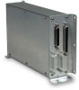
... no field-repairable components. A 44-pin high-density D-subminiature aircraft interface connector provides interfaces to GARMIN for service. 3.0 TECHNICAL SPECIFICATIONS Technical specifications for the GAD 42 are listed in the GAD 42 Installation Manual. 5.0 GENERAL DESCRIPTION The GAD 42 Interface Adapter consists of two internal printed circuit board assemblies, the Analog PC Board and the CPU PC Board. 5.1 Analog...
... no field-repairable components. A 44-pin high-density D-subminiature aircraft interface connector provides interfaces to GARMIN for service. 3.0 TECHNICAL SPECIFICATIONS Technical specifications for the GAD 42 are listed in the GAD 42 Installation Manual. 5.0 GENERAL DESCRIPTION The GAD 42 Interface Adapter consists of two internal printed circuit board assemblies, the Analog PC Board and the CPU PC Board. 5.1 Analog...

