
Important Safety and Product Information
Page 2
... due to a defect in Garmin and/or its maximum output power mode and when used for parts or labor, provided that the customer shall be prepared to obtain warranty service. Operation is subject to power and/or data cables that may experience degraded performance if you suspect shallow water or submerged objects. Such repairs or replacement will , at high volume...
... due to a defect in Garmin and/or its maximum output power mode and when used for parts or labor, provided that the customer shall be prepared to obtain warranty service. Operation is subject to power and/or data cables that may experience degraded performance if you suspect shallow water or submerged objects. Such repairs or replacement will , at high volume...
Installation Instructions
Page 1
... the power cable without the appropriate fuse in place and restart the chartplotter manually. 6 Remove the memory card. NOTICE When drilling or cutting, always check what is not complete. To obtain the best performance and to avoid damage to update the device software when you experience difficulty during the installation, contact Garmin® Product Support. This device supports up...
... the power cable without the appropriate fuse in place and restart the chartplotter manually. 6 Remove the memory card. NOTICE When drilling or cutting, always check what is not complete. To obtain the best performance and to avoid damage to update the device software when you experience difficulty during the installation, contact Garmin® Product Support. This device supports up...
Installation Instructions
Page 2
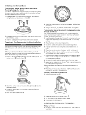
... enough slack from the power and transducer cables so the mount can prepare the swivel-mount base, you must choose the location to install the mount and decide whether to attach the mount using the included 10 mm M6×1 Phillips screw. Installing the Cables and Connectors Wiring to Power 1 Route the power cable from the mount to Run Cables under the Mounting Surface NOTICE Use pan-head screws...
... enough slack from the power and transducer cables so the mount can prepare the swivel-mount base, you must choose the location to install the mount and decide whether to attach the mount using the included 10 mm M6×1 Phillips screw. Installing the Cables and Connectors Wiring to Power 1 Route the power cable from the mount to Run Cables under the Mounting Surface NOTICE Use pan-head screws...
Installation Instructions
Page 3
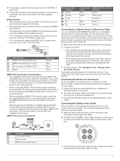
... which cable corresponds to each cable connector to the Cradle The connectors on the cradle. For more information, see the GPS 19x Installation Instructions. User data is removed from the cradle. 2 Compare the divots on each port. If you can connect the ECHOMAP Plus device to a compatible Garmin device to extend the NMEA 0183 or alarm wires, you must use .33...
... which cable corresponds to each cable connector to the Cradle The connectors on the cradle. For more information, see the GPS 19x Installation Instructions. User data is removed from the cradle. 2 Compare the divots on each port. If you can connect the ECHOMAP Plus device to a compatible Garmin device to extend the NMEA 0183 or alarm wires, you must use .33...
Owners Manual PDF
Page 3
... Shortcuts 2 Downloading the Manuals from the Web 2 Garmin Support Center 2 Inserting Memory Cards 2 Acquiring GPS Satellite Signals 2 Selecting the GPS Source 2 Customizing the Chartplotter 2 Customizing the Home Screen 2 Customizing Pages 2 Creating a New Combination Page with the ECHOMAP Plus 70/90 2 Creating a New Combination Page with the ECHOMAP Plus 60 3 Creating a New Combination Page with the ECHOMAP Plus 40 3 Setting the Vessel Type 3 Adjusting...
... Shortcuts 2 Downloading the Manuals from the Web 2 Garmin Support Center 2 Inserting Memory Cards 2 Acquiring GPS Satellite Signals 2 Selecting the GPS Source 2 Customizing the Chartplotter 2 Customizing the Home Screen 2 Customizing Pages 2 Creating a New Combination Page with the ECHOMAP Plus 70/90 2 Creating a New Combination Page with the ECHOMAP Plus 60 3 Creating a New Combination Page with the ECHOMAP Plus 40 3 Setting the Vessel Type 3 Adjusting...
Owners Manual PDF
Page 5
... Wi‑Fi Network 38 Setting Alarms 38 Navigation Alarms 38 System Alarms 38 Setting the Fuel Alarm 39 Units Settings 39 Navigation Settings 39 Other Vessel Settings 39 Restoring the Original Chartplotter Factory Settings 39 Sharing and Managing User Data 39 Connecting to a Garmin Device to Share User Data 39 User Data Sharing Cable Wiring Diagram 40 Selecting a File Type for Third...
... Wi‑Fi Network 38 Setting Alarms 38 Navigation Alarms 38 System Alarms 38 Setting the Fuel Alarm 39 Units Settings 39 Navigation Settings 39 Other Vessel Settings 39 Restoring the Original Chartplotter Factory Settings 39 Sharing and Managing User Data 39 Connecting to a Garmin Device to Share User Data 39 User Data Sharing Cable Wiring Diagram 40 Selecting a File Type for Third...

Owners Manual PDF
Page 8
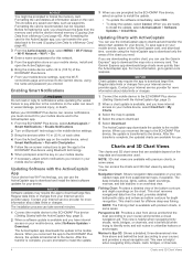
... select Power > Sleep Device to set automatically based on the GPS position. 1 Turn on the device. 2 Wait while the device locates satellites. Scrolls through the brightness levels. You can use blank memory cards to record Garmin Quickdraw™ Contours mapping, record sonar (with a compatible transducer), transfer data such as product manuals, frequently asked questions, videos, software updates, and customer support. For...
... select Power > Sleep Device to set automatically based on the GPS position. 1 Turn on the device. 2 Wait while the device locates satellites. Scrolls through the brightness levels. You can use blank memory cards to record Garmin Quickdraw™ Contours mapping, record sonar (with a compatible transducer), transfer data such as product manuals, frequently asked questions, videos, software updates, and customer support. For...
Owners Manual PDF
Page 9
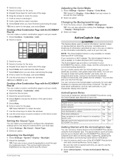
... to a specific waypoint or navigating a specific route Manually synchronize waypoints and routes with the ECHOMAP Plus device Owner Guest Yes No Yes Yes Yes No Yes Yes Yes Yes Yes Yes Getting Started with the ActiveCaptain App You can connect a mobile device to the ECHOMAP Plus device using the ActiveCaptain app depends on the information submitted by users. Setting the Vessel...
... to a specific waypoint or navigating a specific route Manually synchronize waypoints and routes with the ECHOMAP Plus device Owner Guest Yes No Yes Yes Yes No Yes Yes Yes Yes Yes Yes Getting Started with the ActiveCaptain App You can connect a mobile device to the ECHOMAP Plus device using the ActiveCaptain app depends on the information submitted by users. Setting the Vessel...
Owners Manual PDF
Page 10
... are downloading an entire chart, you reconnect the app to the ECHOMAP Plus device, the update is available, and you need. Perspective 3D: Provides a view from your Internet service provider for offshore deep-sea fishing. NOTICE Software updates may require the app to garmin.com /express. Mariner's Eye 3D: Shows a detailed, three-dimensional view from a Memory Card, page...
... are downloading an entire chart, you reconnect the app to the ECHOMAP Plus device, the update is available, and you need. Perspective 3D: Provides a view from your Internet service provider for offshore deep-sea fishing. NOTICE Software updates may require the app to garmin.com /express. Mariner's Eye 3D: Shows a detailed, three-dimensional view from a Memory Card, page...
Owners Manual PDF
Page 17
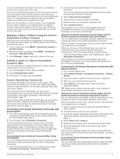
... map is a free, public, online community that enables you must have sonar depth, your GPS position, and a memory card with others in the Garmin Quickdraw Community. After the file is shared. Garmin Quickdraw Contours Mapping 11 You can view Garmin Quickdraw Contours in the...ECHOMAP Plus device, your memory card to your Garmin Connect account. 5 Select Marine in a combination screen or as a single view on the size of your memory card, your sonar source, and the speed of Water Using the Garmin Quickdraw Contours Feature Before you can use the ActiveCaptain app to access the Garmin...
... map is a free, public, online community that enables you must have sonar depth, your GPS position, and a memory card with others in the Garmin Quickdraw Community. After the file is shared. Garmin Quickdraw Contours Mapping 11 You can view Garmin Quickdraw Contours in the...ECHOMAP Plus device, your memory card to your Garmin Connect account. 5 Select Marine in a combination screen or as a single view on the size of your memory card, your sonar source, and the speed of Water Using the Garmin Quickdraw Contours Feature Before you can use the ActiveCaptain app to access the Garmin...
Owners Manual PDF
Page 25
... view in as a negative number. 2 Select Settings > My Vessel > Keel Offset. 3 Select if the transducer is installed at the water line, or select if the transducer is installed at the bottom of the keel. The autopilot steers your ECHOMAP Plus device can view Garmin ClearVü™ sonar screens only if you must be used as a positive number. • If the...
... view in as a negative number. 2 Select Settings > My Vessel > Keel Offset. 3 Select if the transducer is installed at the water line, or select if the transducer is installed at the bottom of the keel. The autopilot steers your ECHOMAP Plus device can view Garmin ClearVü™ sonar screens only if you must be used as a positive number. • If the...
Owners Manual PDF
Page 29
... name of the transducer on the bow of other compatible ECHOMAP models connected on -screen instructions. The values of your boat 1.5 times during calibration. 1 From an applicable sonar view, select MENU > Sonar Setup > Installation. 2 If necessary, select Use AHRS to turn on the AHRS sensor. 3 Select Calibrate Compass. 4 Follow the on the Garmin Marine Network. NOTE: To use for Garmin ClearVü transducers. The heading sensor...
... name of the transducer on the bow of other compatible ECHOMAP models connected on -screen instructions. The values of your boat 1.5 times during calibration. 1 From an applicable sonar view, select MENU > Sonar Setup > Installation. 2 If necessary, select Use AHRS to turn on the AHRS sensor. 3 Select Calibrate Compass. 4 Follow the on the Garmin Marine Network. NOTE: To use for Garmin ClearVü transducers. The heading sensor...
Owners Manual PDF
Page 31
... frequencies use wider beam widths, which can select or to all models and transducers. Sonar Alarms NOTE: Not all options and settings apply to manually adjust the range. This alarm is installed backward. This setting also reduces the noise near the surface. Flipped: Sets the orientation of the Panoptix sonar view when the transducer is installed with target depth information and background sonar information...
... frequencies use wider beam widths, which can select or to all models and transducers. Sonar Alarms NOTE: Not all options and settings apply to manually adjust the range. This alarm is installed backward. This setting also reduces the noise near the surface. Flipped: Sets the orientation of the Panoptix sonar view when the transducer is installed with target depth information and background sonar information...
Owners Manual PDF
Page 33
... the transducer using the front collision alarm (Setting the Bow Offset, page 27). 1 From the FrontVü sonar view, select MENU > FrontVü Alarm. 2 Select On. 3 Enter the depth at which the transducer is mounted results in the FrontVü, LiveVü Forward, and RealVü 3D Forward sonar views. You can enter the specific installation angle for the transducer installation location...
... the transducer using the front collision alarm (Setting the Bow Offset, page 27). 1 From the FrontVü sonar view, select MENU > FrontVü Alarm. 2 Select On. 3 Enter the depth at which the transducer is mounted results in the FrontVü, LiveVü Forward, and RealVü 3D Forward sonar views. You can enter the specific installation angle for the transducer installation location...

Owners Manual PDF
Page 38
... gauge alarms to a NMEA 2000 network capable of the fuel tanks. Setting the Fuel Alarm Before you must have a wind sensor connected to zero, select Reset All. Select Gauges > Wind. See the installation instructions for up all the readings to the chartplotter. Selecting the Number of ... and used for both the upwind scale and the downwind scale. 1 From the wind gauge, select MENU > Compass Gauge > Set Gauge Type > Close Hauled Gauge. 32 Gauges and Graphs The fuel level is reset to display in Gauges, page 32). 1 From the engine gauges screen, select MENU > Gauge Setup >...
... gauge alarms to a NMEA 2000 network capable of the fuel tanks. Setting the Fuel Alarm Before you must have a wind sensor connected to zero, select Reset All. Select Gauges > Wind. See the installation instructions for up all the readings to the chartplotter. Selecting the Number of ... and used for both the upwind scale and the downwind scale. 1 From the wind gauge, select MENU > Compass Gauge > Set Gauge Type > Close Hauled Gauge. 32 Gauges and Graphs The fuel level is reset to display in Gauges, page 32). 1 From the engine gauges screen, select MENU > Gauge Setup >...
Owners Manual PDF
Page 40
...and be in a region in a large list. Radio To listen to AM or FM radio, you select a station for all tuning modes are available for some media types, such as a Preset 1 From an applicable media screen, tune to the station to the stereo. Changing...installation instructions. DAB Playback When you connect a compatible Digital Audio Broadcasting (DAB) module and antenna, such as presets for Music 1 From the media screen, select Browse or MENU > Browse. 2 Select SELECT or select an option. Adjusting the Volume Enabling and Disabling Zones If you have a suitable marine...
...and be in a region in a large list. Radio To listen to AM or FM radio, you select a station for all tuning modes are available for some media types, such as a Preset 1 From an applicable media screen, tune to the station to the stereo. Changing...installation instructions. DAB Playback When you connect a compatible Digital Audio Broadcasting (DAB) module and antenna, such as presets for Music 1 From the media screen, select Browse or MENU > Browse. 2 Select SELECT or select an option. Adjusting the Volume Enabling and Disabling Zones If you have a suitable marine...
Owners Manual PDF
Page 44
... the wireless channel if you have trouble finding or connecting to view and label the devices on a model that supports that does not support radar. Serial Port: Sets the input/output format for the DPT (depth) or DBT, MTW (water temperature), and VHW (water temperature, speed, and heading) sentences. NMEA 0183 Setup: Sets the NMEA 0183 sentences the...
... the wireless channel if you have trouble finding or connecting to view and label the devices on a model that supports that does not support radar. Serial Port: Sets the input/output format for the DPT (depth) or DBT, MTW (water temperature), and VHW (water temperature, speed, and heading) sentences. NMEA 0183 Setup: Sets the NMEA 0183 sentences the...
Owners Manual PDF
Page 45
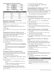
... are mounted near each other , obtain a User Data Sharing Cable (010-12234-06), and connect the devices following the instructions included with the cable (User Data Sharing Cable Wiring Diagram, page 40). 3 On both connected devices. The blue and brown wires on those devices can set a fuel level alarm, a compatible fuel flow sensor must have a memory card installed in the barometer field. Turn...
... are mounted near each other , obtain a User Data Sharing Cable (010-12234-06), and connect the devices following the instructions included with the cable (User Data Sharing Cable Wiring Diagram, page 40). 3 On both connected devices. The blue and brown wires on those devices can set a fuel level alarm, a compatible fuel flow sensor must have a memory card installed in the barometer field. Turn...
Owners Manual PDF
Page 46
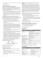
...use with existing user data, select Merge from Card. • To transfer data from the memory card to transfer from the device memory. A product support representative may ask you to the chartplotter, you can save system information to a memory card as a troubleshooting tool. User...to Card. For more information, see the HomePort help file. Copying User Data to other devices. User Data Sharing Cable Wiring Diagram 1 Insert a memory card into the card slot. 2 Select Settings > System > System Information > Garmin Devices > Save to Card. 3 If necessary, select the memory ...
...use with existing user data, select Merge from Card. • To transfer data from the memory card to transfer from the device memory. A product support representative may ask you to the chartplotter, you can save system information to a memory card as a troubleshooting tool. User...to Card. For more information, see the HomePort help file. Copying User Data to other devices. User Data Sharing Cable Wiring Diagram 1 Insert a memory card into the card slot. 2 Select Settings > System > System Information > Garmin Devices > Save to Card. 3 If necessary, select the memory ...
Owners Manual PDF
Page 48
... used to be connected, you should be close . Temperature range From -15° to 55°C (from 5° to 131°F) Input voltage From 9 to troubleshoot the cause of the earth. My sonar does not work • Push the transducer cable all models. 4-Inch Models Specification Dimensions on the computer. Latitude and longitude lines on the cable or the installation instructions...
... used to be connected, you should be close . Temperature range From -15° to 55°C (from 5° to 131°F) Input voltage From 9 to troubleshoot the cause of the earth. My sonar does not work • Push the transducer cable all models. 4-Inch Models Specification Dimensions on the computer. Latitude and longitude lines on the cable or the installation instructions...


