Installation Instructions
Page 2
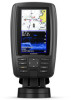
...fuse block. 2 Fastening the Swivel Mount with the Cables Running through the Mount You should complete this procedure only when running the power and transducer cables under the mounting surface and through the swivel-mount base. 1 Feed the cables through the 16 mm (5/8 in.) center hole you drilled...with countersunk heads damage the base. Before you can fully swivel to the desired positions when the cables are not running the power and transducer cables under the Mounting Surface NOTICE Use pan-head screws or bolts when securing the swivel-mount base. Installing the Cradle in the ...
...fuse block. 2 Fastening the Swivel Mount with the Cables Running through the Mount You should complete this procedure only when running the power and transducer cables under the mounting surface and through the swivel-mount base. 1 Feed the cables through the 16 mm (5/8 in.) center hole you drilled...with countersunk heads damage the base. Before you can fully swivel to the desired positions when the cables are not running the power and transducer cables under the Mounting Surface NOTICE Use pan-head screws or bolts when securing the swivel-mount base. Installing the Cradle in the ...
Installation Instructions
Page 3
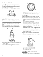
... Data Sharing. Wiring Harness • The wiring harness is necessary to extend the NMEA 0183 or alarm wires, you can connect the ECHOMAP Plus device to a compatible Garmin device to share user data, such as waypoints. The connected cables are mounted too far apart for NMEA® 0183 devices, and ...transmitting (Tx) wires or two receiving (Rx) wires each, it is not necessary for your needs. 1 Follow the instructions provided with your transducer to correctly install it is used to connect to NMEA 0183 compliant devices. • If it is necessary to extend the power and ground wires...
... Data Sharing. Wiring Harness • The wiring harness is necessary to extend the NMEA 0183 or alarm wires, you can connect the ECHOMAP Plus device to a compatible Garmin device to share user data, such as waypoints. The connected cables are mounted too far apart for NMEA® 0183 devices, and ...transmitting (Tx) wires or two receiving (Rx) wires each, it is not necessary for your needs. 1 Follow the instructions provided with your transducer to correctly install it is used to connect to NMEA 0183 compliant devices. • If it is necessary to extend the power and ground wires...

Installation Instructions
Page 4
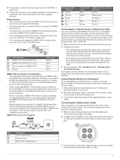
...MTW: Water temperature SDVHW VHW: Water speed and heading 4 For more information, go to www.garmin.com /waterrating. 2Dependent upon transducer and chartplotter model. 3Dependent upon transducer, water salinity, bottom type, and other water conditions. NOTE: If the cables are connected ... A, 125 V fast-acting Input voltage From 9 to 18 Vdc Max. NOTICE You should make sure the bracket is dependent upon transducer. 4Maximum depth is firmly snapped shut. NMEA 0183 Information Transmit Sentence Description GPAPB APB: Heading or track controller (autopilot) sentence "B" ...
...MTW: Water temperature SDVHW VHW: Water speed and heading 4 For more information, go to www.garmin.com /waterrating. 2Dependent upon transducer and chartplotter model. 3Dependent upon transducer, water salinity, bottom type, and other water conditions. NOTE: If the cables are connected ... A, 125 V fast-acting Input voltage From 9 to 18 Vdc Max. NOTICE You should make sure the bracket is dependent upon transducer. 4Maximum depth is firmly snapped shut. NMEA 0183 Information Transmit Sentence Description GPAPB APB: Heading or track controller (autopilot) sentence "B" ...
Installation Instructions
Page 5
The microSD® logo is a trademark of Garmin Ltd. Receive Sentence DPT DBT MTW VHW WPL DSC DSE HDG HDM MWD MDA MWV VDM Description Depth Depth below transducer Water temperature Water speed and heading Waypoint location Digital selective calling information Expanded digital...: NMEA, Seven Riggs Avenue, Severna Park, MD 21146 USA (www.nmea.org) © 2017 Garmin Ltd. ECHOMAP™, Garmin ClearVü™, and Garmin Quickdraw™ are trademarks of Garmin. NMEA® is a registered trademark of the National Marine Electronics Association. or its subsidiaries, registered...
The microSD® logo is a trademark of Garmin Ltd. Receive Sentence DPT DBT MTW VHW WPL DSC DSE HDG HDM MWD MDA MWV VDM Description Depth Depth below transducer Water temperature Water speed and heading Waypoint location Digital selective calling information Expanded digital...: NMEA, Seven Riggs Avenue, Severna Park, MD 21146 USA (www.nmea.org) © 2017 Garmin Ltd. ECHOMAP™, Garmin ClearVü™, and Garmin Quickdraw™ are trademarks of Garmin. NMEA® is a registered trademark of the National Marine Electronics Association. or its subsidiaries, registered...

Owners Manual PDF
Page 4
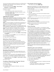
...Sonar Recordings 24 Recording the Sonar Display 24 Stopping the Sonar Recording 24 Deleting a Sonar Recording 24 Playing Sonar Recordings 24 Traditional, Garmin ClearVü, and SideVü Sonar Setup 24 Setting the Zoom Level on the Sonar Screen 24 Setting the Scroll Speed 24...Forward and FrontVü Sonar Menu 26 LiveVü and FrontVü Appearance Settings 27 RealVü Appearance Settings 27 Panoptix Transducer Installation Settings 27 Autopilot 28 Autopilot Screen 28 Adjusting the Step Steering Increment 28 Setting the Power Saver 28 Selecting the Preferred Heading ...
...Sonar Recordings 24 Recording the Sonar Display 24 Stopping the Sonar Recording 24 Deleting a Sonar Recording 24 Playing Sonar Recordings 24 Traditional, Garmin ClearVü, and SideVü Sonar Setup 24 Setting the Zoom Level on the Sonar Screen 24 Setting the Scroll Speed 24...Forward and FrontVü Sonar Menu 26 LiveVü and FrontVü Appearance Settings 27 RealVü Appearance Settings 27 Panoptix Transducer Installation Settings 27 Autopilot 28 Autopilot Screen 28 Adjusting the Step Steering Increment 28 Setting the Power Saver 28 Selecting the Preferred Heading ...
Owners Manual PDF
Page 7
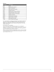
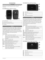
... key Automatic backlight sensor Touchscreen Shortcut keys microSD memory card slot Introduction 1 ECHOMAP Plus 40 Device View ECHOMAP Plus 60 Front View Power key Automatic backlight sensor Keys microSD memory card slot Device keys microSD® memory card slot Power and transducer connectors Beeper NOTICE Each time you place the device in the bracket, you...
... key Automatic backlight sensor Touchscreen Shortcut keys microSD memory card slot Introduction 1 ECHOMAP Plus 40 Device View ECHOMAP Plus 60 Front View Power key Automatic backlight sensor Keys microSD memory card slot Device keys microSD® memory card slot Power and transducer connectors Beeper NOTICE Each time you place the device in the bracket, you...

Owners Manual PDF
Page 8
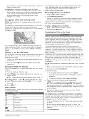
... shortcut is so low you have added to scroll through the brightness levels when pressed repeatedly. 1 2 3 4 Assigns a shortcut key to garmin.com/manuals/echomapplus60-70-90. 2 Download the manual. Selecting the GPS Source You can get the latest owner's manual and translations of manuals ...with a compatible transducer), transfer data such as adjusting the backlight and locking the touchscreen. • Press , and select Power > Turn Off Device, or hold until it clicks. 4 Close the door. You can create a shortcut to the Frequently Used category with the ECHOMAP Plus 70/90 You...
... shortcut is so low you have added to scroll through the brightness levels when pressed repeatedly. 1 2 3 4 Assigns a shortcut key to garmin.com/manuals/echomapplus60-70-90. 2 Download the manual. Selecting the GPS Source You can get the latest owner's manual and translations of manuals ...with a compatible transducer), transfer data such as adjusting the backlight and locking the touchscreen. • Press , and select Power > Turn Off Device, or hold until it clicks. 4 Close the door. You can create a shortcut to the Frequently Used category with the ECHOMAP Plus 70/90 You...
Owners Manual PDF
Page 11
... at the bottom of the Auto Guidance line. Fish Eye 3D: Provides an underwater view that may pass over land or shallow water. When a sonar transducer is indicated by red, green, and yellow spheres. Navigation Chart and Fishing Chart NOTE: The Fishing chart is optimized for use the arrow keys. 2 Select...
... at the bottom of the Auto Guidance line. Fish Eye 3D: Provides an underwater view that may pass over land or shallow water. When a sonar transducer is indicated by red, green, and yellow spheres. Navigation Chart and Fishing Chart NOTE: The Fishing chart is optimized for use the arrow keys. 2 Select...

Owners Manual PDF
Page 16
...between 16 and 32 km/h (10 and 20 mph). View: Sets the perspective of the bottom. If you have multiple depth range shading by the transducer. A yellow circle indicates good depth and GPS position, and a speed between . Waypoints: Shows waypoints on the chart, and shows the AIS list. ...depth. Fish Symbols: Shows suspended targets. If you to help show the density of the 3D chart view. Any use while fishing. The Garmin Quickdraw Contours mapping feature allows you purchase maps from the shoreline to ten depth ranges. A red circle indicates poor depth or GPS position, ...
...between 16 and 32 km/h (10 and 20 mph). View: Sets the perspective of the bottom. If you have multiple depth range shading by the transducer. A yellow circle indicates good depth and GPS position, and a speed between . Waypoints: Shows waypoints on the chart, and shows the AIS list. ...depth. Fish Symbols: Shows suspended targets. If you to help show the density of the 3D chart view. Any use while fishing. The Garmin Quickdraw Contours mapping feature allows you purchase maps from the shoreline to ten depth ranges. A red circle indicates poor depth or GPS position, ...

Owners Manual PDF
Page 24
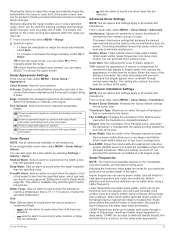
...angle, enter a higher number. For a smoother layline that display a higher sensitivity to set a layline based on your boat and the transducer is white. For laylines that filters out some of the water, depending on the leeward sailing angle. Laylines can display laylines on the ... To switch the position of your needs. Setting the Distance between the Bow and the GPS Antenna You can use features customized for the transducer installation location. Tide Correction: Corrects the laylines based on the chart, and sets the length of your boat type. 1 Select Settings >...
...angle, enter a higher number. For a smoother layline that display a higher sensitivity to set a layline based on your boat and the transducer is white. For laylines that filters out some of the water, depending on the leeward sailing angle. Laylines can display laylines on the ... To switch the position of your needs. Setting the Distance between the Bow and the GPS Antenna You can use features customized for the transducer installation location. Tide Correction: Corrects the laylines based on the chart, and sets the length of your boat type. 1 Select Settings >...
Owners Manual PDF
Page 25
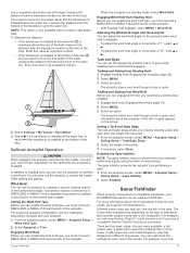
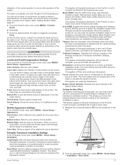
...You can set the autopilot to maintain a specific bearing relative to the current wind angle. The autopilot steers your needs, go to garmin.com/transducers. The gybe inhibitor prevents the autopilot from Wind Hold Before you view the fish in the area. For more views, a split...view Garmin ClearVü™ sonar screens only if you can engage wind hold or . Adjusting the Wind Hold Angle with your ECHOMAP Plus device can adjust the wind hold (Engaging Wind Hold, page 19). 2 Select MENU. 3 Select an option. Sonar Fishfinder When properly connected to a compatible transducer, your...
...You can set the autopilot to maintain a specific bearing relative to the current wind angle. The autopilot steers your needs, go to garmin.com/transducers. The gybe inhibitor prevents the autopilot from Wind Hold Before you view the fish in the area. For more views, a split...view Garmin ClearVü™ sonar screens only if you can engage wind hold or . Adjusting the Wind Hold Angle with your ECHOMAP Plus device can adjust the wind hold (Engaging Wind Hold, page 19). 2 Select MENU. 3 Select an option. Sonar Fishfinder When properly connected to a compatible transducer, your...

Owners Manual PDF
Page 26
... side of the boat Right side of the boat The transducer on the same screen. Changing the Sonar View 1 From a combination screen with the ECHOMAP Plus 70/90, page 2). For information about compatible transducers, go to suit your boat. 20 Sonar Fishfinder The Garmin ClearVü scanning sonar technology emits two narrow beams, similar to...
... side of the boat Right side of the boat The transducer on the same screen. Changing the Sonar View 1 From a combination screen with the ECHOMAP Plus 70/90, page 2). For information about compatible transducers, go to suit your boat. 20 Sonar Fishfinder The Garmin ClearVü scanning sonar technology emits two narrow beams, similar to...

Owners Manual PDF
Page 27
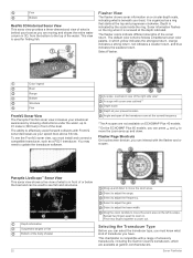
... a two-dimensional view of or below your boat. The RealVü 3D sonar views provide three-dimensional views of either in front of the transducer. This view can be used to see what is around the boat in front of what is below your boat. Color legend Boat Sonar beam... your boat. Color legend Boat Ping indicator Fish Bottom Range Panoptix down views and a second transducer to see the bottom and the fish approaching the boat. The Panoptix sonar views allow you need one transducer to see all five Panoptix sonar views, you to show the forward views. To see all...
... a two-dimensional view of or below your boat. The RealVü 3D sonar views provide three-dimensional views of either in front of the transducer. This view can be used to see what is around the boat in front of what is below your boat. Color legend Boat Sonar beam... your boat. Color legend Boat Ping indicator Fish Bottom Range Panoptix down views and a second transducer to see the bottom and the fish approaching the boat. The Panoptix sonar views allow you need one transducer to see all five Panoptix sonar views, you to show the forward views. To see all...
Owners Manual PDF
Page 28
.... Select to zoom out. Pinch two fingers together to adjust the range. Selecting the Transducer Type Before you can interact with a range of accessory transducers, including the Garmin ClearVü transducers, which yellow indicates the strongest return, orange indicates a strong return, red indicates a ...scale Depth at garmin.com/transducers. Select to adjust the gain. This view is in . Flasher View The flasher shows sonar information on a circular depth scale, indicating what is used to move the zoom area on ECHOMAP Plus 40 models. **On the ECHOMAP Plus 60 models, you...
.... Select to zoom out. Pinch two fingers together to adjust the range. Selecting the Transducer Type Before you can interact with a range of accessory transducers, including the Garmin ClearVü transducers, which yellow indicates the strongest return, orange indicates a strong return, red indicates a ...scale Depth at garmin.com/transducers. Select to adjust the gain. This view is in . Flasher View The flasher shows sonar information on a circular depth scale, indicating what is used to move the zoom area on ECHOMAP Plus 40 models. **On the ECHOMAP Plus 60 models, you...
Owners Manual PDF
Page 29
... to use from another location. Sonar Fishfinder 23 Calibration must mount the transducer on the screen at the selected location. 4 Select another ECHOMAP Plus device and Garmin ClearVü transducer mounted at the back of your boat. The heading sensor shows the direction the transducer is listed in the upper-left corner. For example, if you...
... to use from another location. Sonar Fishfinder 23 Calibration must mount the transducer on the screen at the selected location. 4 Select another ECHOMAP Plus device and Garmin ClearVü transducer mounted at the back of your boat. The heading sensor shows the direction the transducer is listed in the upper-left corner. For example, if you...

Owners Manual PDF
Page 30
...is available for structure, it is displayed on screen. Sonar Recordings Recording the Sonar Display NOTE: Not all models, sounder modules, and transducers. Traditional, Garmin ClearVü, and SideVü Sonar Setup NOTE: Not all options and settings apply to use the default setting, select Default. ... more options. • To set the depth range of the screen, select Magnify. This can select for Garmin ClearVü and SideVü/ClearVü transducers. When viewing Garmin ClearVü or SideVü sonar views or searching for SideVü sonar view. This setting works best...
...is available for structure, it is displayed on screen. Sonar Recordings Recording the Sonar Display NOTE: Not all models, sounder modules, and transducers. Traditional, Garmin ClearVü, and SideVü Sonar Setup NOTE: Not all options and settings apply to use the default setting, select Default. ... more options. • To set the depth range of the screen, select Magnify. This can select for Garmin ClearVü and SideVü/ClearVü transducers. When viewing Garmin ClearVü or SideVü sonar views or searching for SideVü sonar view. This setting works best...
Owners Manual PDF
Page 31
...has minimal or moderate terrain changes. When this setting is available only with the cables pointing toward the port side of the Panoptix transducer. Sonar Fishfinder 25 Allowing the device to adjust the range automatically keeps the bottom within the range you have set. 1 From.... Restore Sonar Defaults: Restores the factory default settings for locating fish. Flipped: Sets the orientation of the Panoptix sonar view when the transducer is installed at a 45-degree angle. Wider beam widths allow you can appear on all options are better for deep water applications. ...
...has minimal or moderate terrain changes. When this setting is available only with the cables pointing toward the port side of the Panoptix transducer. Sonar Fishfinder 25 Allowing the device to adjust the range automatically keeps the bottom within the range you have set. 1 From.... Restore Sonar Defaults: Restores the factory default settings for locating fish. Flipped: Sets the orientation of the Panoptix sonar view when the transducer is installed at a 45-degree angle. Wider beam widths allow you can appear on all options are better for deep water applications. ...

Owners Manual PDF
Page 32
... view, select MENU > Frequency. 2 Select Add. 3 Enter a frequency. Creating a Frequency Preset NOTE: Not available with RealVü capable Panoptix transducers, such as a drop-offs or cliffs. Turning On the A-Scope NOTE: This feature is available only with the lower frequency return and, at the... you want to low depth readings. The a-scope above shows fish returns and a soft bottom return . Sonar Transmit: Stops the active transducer from the higher frequency return. A slower sweep rate creates a more information on the screen, you to view a specified range. Manually ...
... view, select MENU > Frequency. 2 Select Add. 3 Enter a frequency. Creating a Frequency Preset NOTE: Not available with RealVü capable Panoptix transducers, such as a drop-offs or cliffs. Turning On the A-Scope NOTE: This feature is available only with the lower frequency return and, at the... you want to low depth readings. The a-scope above shows fish returns and a soft bottom return . Sonar Transmit: Stops the active transducer from the higher frequency return. A slower sweep rate creates a more information on the screen, you to view a specified range. Manually ...
Owners Manual PDF
Page 33
... 8 knots. The trails show the movement of sound. Install Depth: Sets the depth below a specified level. Orientation: Controls if the transducer is in a more coverage area. The Auto setting uses the temperature of the water to calculate the speed of the target. CAUTION The..., select MENU > Sonar Setup > Installation > Bow Offset. This applies to the factory default values. Focus: Adjusts the sonar view to compensate for the transducer using the front collision alarm (Setting the Bow Offset, page 27). 1 From the FrontVü sonar view, select MENU > FrontVü Alarm. 2...
... 8 knots. The trails show the movement of sound. Install Depth: Sets the depth below a specified level. Orientation: Controls if the transducer is in a more coverage area. The Auto setting uses the temperature of the water to calculate the speed of the target. CAUTION The..., select MENU > Sonar Setup > Installation > Bow Offset. This applies to the factory default values. Focus: Adjusts the sonar view to compensate for the transducer using the front collision alarm (Setting the Bow Offset, page 27). 1 From the FrontVü sonar view, select MENU > FrontVü Alarm. 2...

Owners Manual PDF
Page 37
...-report call. 3 Select Navigate To. 4 Select Go To or Route To. Every position report call received is 72. To view the information, a compatible transducer or sensor must be connected to a Tracked Vessel 1 Select Nav Info > Other Vessels > DSC List. 2 Select a position-report call . Select Gauges ...the call . 3 Select Call with Radio > Channel. 4 Select an available channel. Individual Routine Calls When you connect the chartplotter to a Garmin VHF radio, you can use the chartplotter interface to a VHF radio using the compass. Making an Individual Routine Call NOTE: When initiating a ...
...-report call. 3 Select Navigate To. 4 Select Go To or Route To. Every position report call received is 72. To view the information, a compatible transducer or sensor must be connected to a Tracked Vessel 1 Select Nav Info > Other Vessels > DSC List. 2 Select a position-report call . Select Gauges ...the call . 3 Select Call with Radio > Channel. 4 Select an available channel. Individual Routine Calls When you connect the chartplotter to a Garmin VHF radio, you can use the chartplotter interface to a VHF radio using the compass. Making an Individual Routine Call NOTE: When initiating a ...


