Manual/User Guide
Page 3
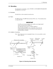
... surface 2.5 mounting PCA B Frame of system cabinet 3.0 or less Screw Details of A 3.0 or less Screw Details of the HDD disk enclosure (DE) is not possible to SG. When attaching the HDD to the system frame, do not allow the system frame to touch parts (cover and base) other than parts to... C141-E250 3-3 if it is zero. The tightening torque must be mounted in Figure 3.2. 3.2 Mounting 3.2 Mounting For information on mounting, see the "FUJITSU 2.5-INCH HDD INTEGRATION GUIDANCE (C141-E144)." (1) Orientation The disk drives can be 0.49N•m (5kgf•cm).
... surface 2.5 mounting PCA B Frame of system cabinet 3.0 or less Screw Details of A 3.0 or less Screw Details of the HDD disk enclosure (DE) is not possible to SG. When attaching the HDD to the system frame, do not allow the system frame to touch parts (cover and base) other than parts to... C141-E250 3-3 if it is zero. The tightening torque must be mounted in Figure 3.2. 3.2 Mounting 3.2 Mounting For information on mounting, see the "FUJITSU 2.5-INCH HDD INTEGRATION GUIDANCE (C141-E144)." (1) Orientation The disk drives can be 0.49N•m (5kgf•cm).
Manual/User Guide
Page 4
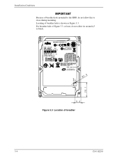
Locating of breather 3-4 C141-E250 For breather hole of Figure 3.3, at least, do not allow its around φ 3 to close during mounting. Figure 3.3 Location of breather hole is shown as Figure 3.3. Installation Conditions Because of breather hole mounted to the HDD, do not allow this to block.
Locating of breather 3-4 C141-E250 For breather hole of Figure 3.3, at least, do not allow its around φ 3 to close during mounting. Figure 3.3 Location of breather hole is shown as Figure 3.3. Installation Conditions Because of breather hole mounted to the HDD, do not allow this to block.
Manual/User Guide
Page 6
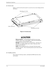
...the device, disconnect the body ground (500 kΩ or greater). Ensure that the disk drive is not affected by the edges. (6) Handling cautions Please keep the following cautions, and handle the HDD under the safety environment. 3-6 C141-E250 Mounting screw hole Cable connection Mounting screw hole Figure ...Do not touch the printed circuit board, but hold it too hard, the cover and the spindle motor contact, which may cause damage to the disk drive. Damage: Do not press the cover of the disk drive. Pressing it by external magnetic fields. Installation Conditions (5) Service area...
...the device, disconnect the body ground (500 kΩ or greater). Ensure that the disk drive is not affected by the edges. (6) Handling cautions Please keep the following cautions, and handle the HDD under the safety environment. 3-6 C141-E250 Mounting screw hole Cable connection Mounting screw hole Figure ...Do not touch the printed circuit board, but hold it too hard, the cover and the spindle motor contact, which may cause damage to the disk drive. Damage: Do not press the cover of the disk drive. Pressing it by external magnetic fields. Installation Conditions (5) Service area...
Manual/User Guide
Page 7
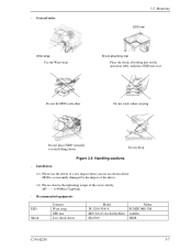
HDD is occasionally damaged by the impact of the driver. (2) Please observe the tightening torque of a low impact when you use the driver of the screw ...-8A (Color Seiden Mat) SS-6500 Maker SUMITOMO 3M Achilles HIOS C141-E250 3-7 Installation (1) Please use an electric driver. Figure 3.6 Handling cautions - Do not hit HDD each other. Do not drop. - General notes Wrist strap Use the Wrist strap. 3.2 Mounting ESD mat Shock absorbing mat Place the shock absorbing mat on...
HDD is occasionally damaged by the impact of the driver. (2) Please observe the tightening torque of a low impact when you use the driver of the screw ...-8A (Color Seiden Mat) SS-6500 Maker SUMITOMO 3M Achilles HIOS C141-E250 3-7 Installation (1) Please use an electric driver. Figure 3.6 Handling cautions - Do not hit HDD each other. Do not drop. - General notes Wrist strap Use the Wrist strap. 3.2 Mounting ESD mat Shock absorbing mat Place the shock absorbing mat on...


