Manual/User Guide
Page 3
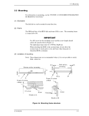
... HDD is connected to satisfy them, contact us. 3.2 Mounting 3.2 Mounting For information on mounting, see the "FUJITSU 2.5-INCH HDD INTEGRATION GUIDANCE (C141-E144)." (1) Orientation The disk drives can be 0.49N•m (5kgf•cm). The mounting frame is attached. (3) Limitation of B Figure 3.2... Mounting frame structure C141-E250 3-3 if it is zero. Use M3 screw for the mounting screw and the screw length should satisfy the specification in any direction...
... HDD is connected to satisfy them, contact us. 3.2 Mounting 3.2 Mounting For information on mounting, see the "FUJITSU 2.5-INCH HDD INTEGRATION GUIDANCE (C141-E144)." (1) Orientation The disk drives can be 0.49N•m (5kgf•cm). The mounting frame is attached. (3) Limitation of B Figure 3.2... Mounting frame structure C141-E250 3-3 if it is zero. Use M3 screw for the mounting screw and the screw length should satisfy the specification in any direction...
Manual/User Guide
Page 9
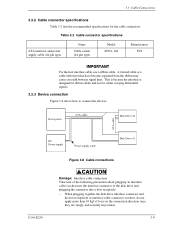
... together the disk drive interface connector and the host receptacle or interface cable connector (socket), do not apply more than 10 kgf of force in the connection direction once they are snugly and securely in position. 3-9 Table 3.2 Cable connector specifications ATA interface and... that have become separated from the ribbon may cause crosstalk between signal lines. 3.3 Cable Connections 3.3.2 Cable connector specifications Table 3.2 lists the recommended specifications for cables carrying differential signals. 3.3.3 Device connection Figure 3.8 shows how to connect the devices.
... together the disk drive interface connector and the host receptacle or interface cable connector (socket), do not apply more than 10 kgf of force in the connection direction once they are snugly and securely in position. 3-9 Table 3.2 Cable connector specifications ATA interface and... that have become separated from the ribbon may cause crosstalk between signal lines. 3.3 Cable Connections 3.3.2 Cable connector specifications Table 3.2 lists the recommended specifications for cables carrying differential signals. 3.3.3 Device connection Figure 3.8 shows how to connect the devices.
