Manual/User Guide
Page 14
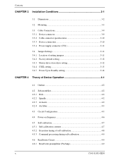
Contents CHAPTER 3 Installation Conditions 3-1 3.1 Dimensions 3-2 3.2 Mounting 3-3 3.3 Cable Connections 3-9 3.3.1 Device connector 3-9 3.3.2 Cable connector specifications 3-10 3.3.3 Device connection 3-10 3.3.4 Power supply connector (CN1 3-11 3.4 Jumper Settings 3-11 3.4.1 Location of setting jumpers 3-11 3.4.2 Factory default setting 3-12 3.4.3 Master drive-slave drive setting 3-12 3.4.4 CSEL setting 3-13 3.4.5 Power Up in Standby setting 3-14 CHAPTER 4 Theory of Device...
Contents CHAPTER 3 Installation Conditions 3-1 3.1 Dimensions 3-2 3.2 Mounting 3-3 3.3 Cable Connections 3-9 3.3.1 Device connector 3-9 3.3.2 Cable connector specifications 3-10 3.3.3 Device connection 3-10 3.3.4 Power supply connector (CN1 3-11 3.4 Jumper Settings 3-11 3.4.1 Location of setting jumpers 3-11 3.4.2 Factory default setting 3-12 3.4.3 Master drive-slave drive setting 3-12 3.4.4 CSEL setting 3-13 3.4.5 Power Up in Standby setting 3-14 CHAPTER 4 Theory of Device...
Manual/User Guide
Page 18
... 3-7 Figure 3.7 Handling cautions 3-8 Figure 3.8 Connector locations 3-9 Figure 3.9 Cable connections 3-10 Figure 3.10 Power supply connector pins (CN1 3-11 Figure 3.11 Jumper location 3-11 Figure 3.12 Factory default setting 3-12 Figure 3.13 Jumper setting of master or slave drive 3-12 Figure 3.14 CSEL setting 3-13 Figure 3.15 Example (1) of Cable Select 3-13 Figure...
... 3-7 Figure 3.7 Handling cautions 3-8 Figure 3.8 Connector locations 3-9 Figure 3.9 Cable connections 3-10 Figure 3.10 Power supply connector pins (CN1 3-11 Figure 3.11 Jumper location 3-11 Figure 3.12 Factory default setting 3-12 Figure 3.13 Jumper setting of master or slave drive 3-12 Figure 3.14 CSEL setting 3-13 Figure 3.15 Example (1) of Cable Select 3-13 Figure...
Manual/User Guide
Page 39
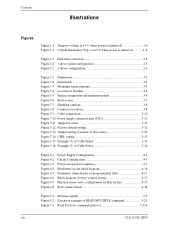
C141-E144 C141-E192-02EN 3-1 CHAPTER 3 Installation Conditions 3.1 Dimensions 3.2 Mounting 3.3 Cable Connections 3.4 Jumper Settings This chapter gives the external dimensions, installation conditions, surface temperature conditions, cable connections, and switch settings of the hard disk drives. For information about handling this hard disk drive and the system installation procedure, refer to the following Integration Guide.
C141-E144 C141-E192-02EN 3-1 CHAPTER 3 Installation Conditions 3.1 Dimensions 3.2 Mounting 3.3 Cable Connections 3.4 Jumper Settings This chapter gives the external dimensions, installation conditions, surface temperature conditions, cable connections, and switch settings of the hard disk drives. For information about handling this hard disk drive and the system installation procedure, refer to the following Integration Guide.
Manual/User Guide
Page 49
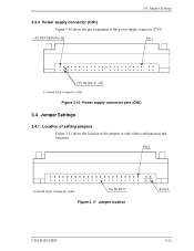
3.4 Jumper Settings 3.3.4 Power supply connector (CN1) Figure 3.10 shows the pin assignment of the jumpers to select drive configuration and functions. Figure 3.11 Jumper location C141-E192-02EN 3-11 Figure 3.10 Power supply connector pins (CN1) 3.4 Jumper Settings 3.4.1 Location of setting jumpers Figure 3.11 shows the location of the power supply connector (CN1).
3.4 Jumper Settings 3.3.4 Power supply connector (CN1) Figure 3.10 shows the pin assignment of the jumpers to select drive configuration and functions. Figure 3.11 Jumper location C141-E192-02EN 3-11 Figure 3.10 Power supply connector pins (CN1) 3.4 Jumper Settings 3.4.1 Location of setting jumpers Figure 3.11 shows the location of the power supply connector (CN1).
Manual/User Guide
Page 50
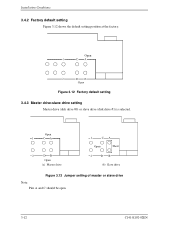
Open Figure 3.12 Factory default setting 3.4.3 Master drive-slave drive setting Master drive (disk drive #0) or slave drive (disk drive #1) is selected. Installation Conditions 3.4.2 Factory default setting Figure 3.12 shows the default setting position at the factory. Open 1 CA 2 DB Open (a) Master drive 1 CA Open Short 2 DB (b) Slave drive Figure 3.13 Jumper setting of master or slave drive Note: Pins A and C should be open. 3-12 C141-E192-02EN
Open Figure 3.12 Factory default setting 3.4.3 Master drive-slave drive setting Master drive (disk drive #0) or slave drive (disk drive #1) is selected. Installation Conditions 3.4.2 Factory default setting Figure 3.12 shows the default setting position at the factory. Open 1 CA 2 DB Open (a) Master drive 1 CA Open Short 2 DB (b) Slave drive Figure 3.13 Jumper setting of master or slave drive Note: Pins A and C should be open. 3-12 C141-E192-02EN
Manual/User Guide
Page 51
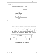
... as a slave drive. drive drive Figure 3.15 Example (1) of cable selection using unique interface cables. 3.4.4 CSEL setting Figure 3.14 shows the cable select (CSEL) setting. 3.4 Jumper Settings Open 1 CA 2 DB Short Note: The CSEL setting is identified as a master drive. At this time, the CSEL of the cable and connecting it...
... as a slave drive. drive drive Figure 3.15 Example (1) of cable selection using unique interface cables. 3.4.4 CSEL setting Figure 3.14 shows the cable select (CSEL) setting. 3.4 Jumper Settings Open 1 CA 2 DB Short Note: The CSEL setting is identified as a master drive. At this time, the CSEL of the cable and connecting it...

Manual/User Guide
Page 116
...for deciding the device No. FE-C0: Performance mode BF-80: Acoustic mode 00: Acoustic management is unused it. (It is same as WORD 60-61 is supported, same number of Device 0. '00' = Reserved '01' = Using a jumper. '10' = Using the CSEL signal. '11' = ... Reserved 5-42 C141-E192-02EN Bit 5: '1' = Device 0, assertion of PDIAG- Bit 7-0: X'XX' Current set . was detected. Interface '00' = Reserved '01' = Using a jumper. '10' = Using the CSEL signal. '11' = Other method. Bit 4: '1' = Device 0, assertion of DASP- Bit 8: = '1' (In the case of device 1) Bits ...
...for deciding the device No. FE-C0: Performance mode BF-80: Acoustic mode 00: Acoustic management is unused it. (It is same as WORD 60-61 is supported, same number of Device 0. '00' = Reserved '01' = Using a jumper. '10' = Using the CSEL signal. '11' = ... Reserved 5-42 C141-E192-02EN Bit 5: '1' = Device 0, assertion of PDIAG- Bit 7-0: X'XX' Current set . was detected. Interface '00' = Reserved '01' = Using a jumper. '10' = Using the CSEL signal. '11' = Other method. Bit 4: '1' = Device 0, assertion of DASP- Bit 8: = '1' (In the case of device 1) Bits ...

