Manual/User Guide
Page 5
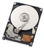
... disk drive. CHAPTER 5 Interface This chapter describes the interface specifications of the disk drive. Glossary The glossary describes the technical terms that is compatible with the ATA interface. C141-E192-02EN i CHAPTER 3 Installation Conditions This chapter describes the external dimensions, installation conditions, and switch settings of the disk drive. Acronyms and Abbreviations This section gives the meanings of the definitions used in this manual. These drives have a built-in controller that need...
... disk drive. CHAPTER 5 Interface This chapter describes the interface specifications of the disk drive. Glossary The glossary describes the technical terms that is compatible with the ATA interface. C141-E192-02EN i CHAPTER 3 Installation Conditions This chapter describes the external dimensions, installation conditions, and switch settings of the disk drive. Acronyms and Abbreviations This section gives the meanings of the definitions used in this manual. These drives have a built-in controller that need...
Manual/User Guide
Page 18
... 3.12 Factory default setting 3-12 Figure 3.13 Jumper setting of master or slave drive 3-12 Figure 3.14 CSEL setting 3-13 Figure 3.15 Example (1) of Cable Select 3-13 Figure 3.16 Example (2) of Cable Select 3-14 Figure 4.1 Figure 4.2 Figure 4.3 Figure 4.4 Figure 4.5 Figure 4.6 Figure 4.7 Figure 4.8 Power Supply Configuration 4-4 Circuit Configuration 4-5 Power-on operation sequence 4-7 Read/write circuit block diagram 4-10 Frequency characteristic of programmable filter 4-11 Block diagram of servo control circuit 4-13 Physical sector servo configuration on disk surface...
... 3.12 Factory default setting 3-12 Figure 3.13 Jumper setting of master or slave drive 3-12 Figure 3.14 CSEL setting 3-13 Figure 3.15 Example (1) of Cable Select 3-13 Figure 3.16 Example (2) of Cable Select 3-14 Figure 4.1 Figure 4.2 Figure 4.3 Figure 4.4 Figure 4.5 Figure 4.6 Figure 4.7 Figure 4.8 Power Supply Configuration 4-4 Circuit Configuration 4-5 Power-on operation sequence 4-7 Read/write circuit block diagram 4-10 Frequency characteristic of programmable filter 4-11 Block diagram of servo control circuit 4-13 Physical sector servo configuration on disk surface...
Manual/User Guide
Page 20
...names and product numbers 1-5 Current and power dissipation 1-7 Environmental specifications 1-8 Acoustic noise specification 1-9 Shock and vibration specification 1-9 Table 3.1 Surface temperature measurement points and standard values..........3-6 Table 3.2 Cable connector specifications 3-10 Table 5.1 Signal assignment on the interface connector 5-3 Table 5.2 I/O registers 5-7 Table 5.3 Command code and parameters 5-15 Table 5.4 Information to be read by IDENTIFY DEVICE command 5-34 Table 5.5 Features register values and settable modes 5-44 Table 5.6 Diagnostic code 5-56 Table...
...names and product numbers 1-5 Current and power dissipation 1-7 Environmental specifications 1-8 Acoustic noise specification 1-9 Shock and vibration specification 1-9 Table 3.1 Surface temperature measurement points and standard values..........3-6 Table 3.2 Cable connector specifications 3-10 Table 5.1 Signal assignment on the interface connector 5-3 Table 5.2 I/O registers 5-7 Table 5.3 Command code and parameters 5-15 Table 5.4 Information to be read by IDENTIFY DEVICE command 5-34 Table 5.5 Features register values and settable modes 5-44 Table 5.6 Diagnostic code 5-56 Table...
Manual/User Guide
Page 25
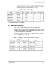
... C141-E192-02EN 1-5 of BIOS parameter. 1.2 Device Specifications Table 1.1 lists the formatted capacity, number of logical cylinders, number of heads, and number of sectors of every model for the standard model. Table 1.1 Specifications (2/2) Model Capacity (*1) No. No. of Cylinder MHT2080AT 8.45 GB 16,383 MHT2060AT 8.45 GB 16,383 MHT2040AT 8.45 GB 16,383 MHT2030AT 8.45 GB 16,383 MHT2020AT 8.45 GB 16,383 *1 On using the BIOS setup utility on the host.
... C141-E192-02EN 1-5 of BIOS parameter. 1.2 Device Specifications Table 1.1 lists the formatted capacity, number of logical cylinders, number of heads, and number of sectors of every model for the standard model. Table 1.1 Specifications (2/2) Model Capacity (*1) No. No. of Cylinder MHT2080AT 8.45 GB 16,383 MHT2060AT 8.45 GB 16,383 MHT2040AT 8.45 GB 16,383 MHT2030AT 8.45 GB 16,383 MHT2020AT 8.45 GB 16,383 *1 On using the BIOS setup utility on the host.
Manual/User Guide
Page 30
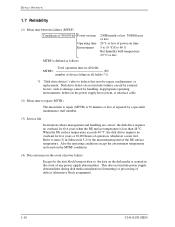
... Device Overview 1.7 Reliability (1) Mean time between failures (MTBF) Conditions of 300,000 h Power-on time Operating time Environment 250H/month or less 3000H/years or less 20 % or less of power-on the disk media is assured in the power supply host system, or interface cable. (2) Mean time to repair (MTTR) The mean time to repair (MTTR) is 30 minutes or less, if repaired by a specialist maintenance staff member. (3) Service...
... Device Overview 1.7 Reliability (1) Mean time between failures (MTBF) Conditions of 300,000 h Power-on time Operating time Environment 250H/month or less 3000H/years or less 20 % or less of power-on the disk media is assured in the power supply host system, or interface cable. (2) Mean time to repair (MTTR) The mean time to repair (MTTR) is 30 minutes or less, if repaired by a specialist maintenance staff member. (3) Service...
Manual/User Guide
Page 31
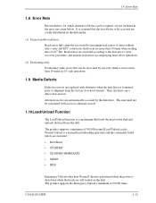
...-free devices. The product supports a minimum of 20,000 times. It is assumed that the data blocks to be accessed are evenly distributed on the disk media. (1) Unrecoverable read error Read errors that can be assigned, are not included in 107 seek operations. 1.9 Media Defects Defective sectors are replaced with access to alternate sectors. 1.10Load/Unload Function The Load/Unload function is a normal head unloading operation and the commands listed below . Read...
...-free devices. The product supports a minimum of 20,000 times. It is assumed that the data blocks to be accessed are evenly distributed on the disk media. (1) Unrecoverable read error Read errors that can be assigned, are not included in 107 seek operations. 1.9 Media Defects Defective sectors are replaced with access to alternate sectors. 1.10Load/Unload Function The Load/Unload function is a normal head unloading operation and the commands listed below . Read...
Manual/User Guide
Page 80
... Cylinder High, Cylinder Low, and Sector Number registers are not asserted. When the DMA data transfer is a 16-bit data transfer. +5 VDC power supplying to the device. and CS1- signals are LBA bits. The sector No. Interface [signal] DMARQ +5 VDC GND [I/O] O I - [Description] This signal is not changed. "O" indicates output signal from the host to the device. When the host system specifies the LBA mode by the INITIALIZE DEVICE PARAMETER command, the sector LBA...
... Cylinder High, Cylinder Low, and Sector Number registers are not asserted. When the DMA data transfer is a 16-bit data transfer. +5 VDC power supplying to the device. and CS1- signals are LBA bits. The sector No. Interface [signal] DMARQ +5 VDC GND [I/O] O I - [Description] This signal is not changed. "O" indicates output signal from the host to the device. When the host system specifies the LBA mode by the INITIALIZE DEVICE PARAMETER command, the sector LBA...
Manual/User Guide
Page 93
... data was not transferred. For the DRQ, INTRQ, and BSY protocols related to the specified track, the device reads the target sector. If an unrecoverable error occurs in the LBA mode) where the error occurred, and remaining number of sectors of sectors can be specified from the address specified in this subsection, bit indication is always set ) Note: 1. Command block registers contain the cylinder, the head...
... data was not transferred. For the DRQ, INTRQ, and BSY protocols related to the specified track, the device reads the target sector. If an unrecoverable error occurs in the LBA mode) where the error occurred, and remaining number of sectors of sectors can be specified from the address specified in this subsection, bit indication is always set ) Note: 1. Command block registers contain the cylinder, the head...
Manual/User Guide
Page 98
... device writes the target sector. After the head reaches to data transfer, see Subsection 5.4.2. Number of sectors can be read) 1F7H(ST) 1F6H(DH) 1F5H(CH) 1F4H(CL) 1F3H(SN) 1F2H(SC) 1F1H(ER) Status information x L x DV End head No. / LBA [MSB] End cylinder No. [MSB] / LBA End cylinder No. [LSB] / LBA End sector No. / LBA [LSB] 00 (*1) Error information *1 If the command is terminated due to an error, the remaining number of sectors...
... device writes the target sector. After the head reaches to data transfer, see Subsection 5.4.2. Number of sectors can be read) 1F7H(ST) 1F6H(DH) 1F5H(CH) 1F4H(CL) 1F3H(SN) 1F2H(SC) 1F1H(ER) Status information x L x DV End head No. / LBA [MSB] End cylinder No. [MSB] / LBA End cylinder No. [LSB] / LBA End sector No. / LBA [LSB] 00 (*1) Error information *1 If the command is terminated due to an error, the remaining number of sectors...
Manual/User Guide
Page 109
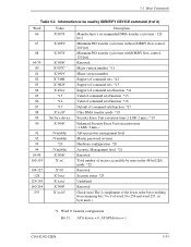
... number Support of command sets *12 Support of command sets *13 Support of command sets/function *14 Valid of command sets/function *15 Valid of command sets/function *16 Default of command sets/function *17 Ultra DMA transfer mode *18 Security Erase Unit execution time (1 LSB: 2 min.) *19 Enhanced Security Erase Unit execution time (1 LSB: 2 min.) Advance power management level Master password revision Hardware configuration *20 Acoustic Management level *21 Reserved Total number of sectors accessible by users in the 48-bit LBA mode *22 Reserved Security...
... number Support of command sets *12 Support of command sets *13 Support of command sets/function *14 Valid of command sets/function *15 Valid of command sets/function *16 Default of command sets/function *17 Ultra DMA transfer mode *18 Security Erase Unit execution time (1 LSB: 2 min.) *19 Enhanced Security Erase Unit execution time (1 LSB: 2 min.) Advance power management level Master password revision Hardware configuration *20 Acoustic Management level *21 Reserved Total number of sectors accessible by users in the 48-bit LBA mode *22 Reserved Security...
Manual/User Guide
Page 112
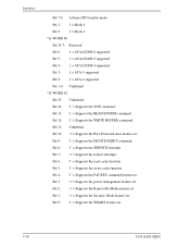
Bit 13: '1' = Supports the READ BUFFER command. Bit 3: '1' = Supports the power management feature set . Interface Bit 7-0: Advance PIO transfer mode Bit 1: 1 = Mode 4 Bit 0: 1 = Mode 3 *11 WORD 80 Bit 15-7: Reserved Bit 6: 1 = ATA/ATAPI-6 supported Bit 5: 1 = ATA/ATAPI-5 supported Bit 4: 1 = ATA/ATAPI-4 supported Bit 3: 1 = ATA-3 supported Bit 2: 1 = ATA-2 supported Bit 1-0: Undefined *12 WORD 82 Bit 15: Undefined Bit 14: '1' = Supports the NOP command. Bit 8: '1' = Supports the SERVICE interrupt. Bit 2: '1' = Supports the Removable Media feature set . Bit 11: Undefined...
Bit 13: '1' = Supports the READ BUFFER command. Bit 3: '1' = Supports the power management feature set . Interface Bit 7-0: Advance PIO transfer mode Bit 1: 1 = Mode 4 Bit 0: 1 = Mode 3 *11 WORD 80 Bit 15-7: Reserved Bit 6: 1 = ATA/ATAPI-6 supported Bit 5: 1 = ATA/ATAPI-5 supported Bit 4: 1 = ATA/ATAPI-4 supported Bit 3: 1 = ATA-3 supported Bit 2: 1 = ATA-2 supported Bit 1-0: Undefined *12 WORD 82 Bit 15: Undefined Bit 14: '1' = Supports the NOP command. Bit 8: '1' = Supports the SERVICE interrupt. Bit 2: '1' = Supports the Removable Media feature set . Bit 11: Undefined...
Manual/User Guide
Page 117
... changing the device features to be set in the Features register. C141-E192-02EN 5-43 If the value in the Features register is not supported or it is invalid, the device posts an ABORTED COMMAND error. 5.3 Host Commands Bit 5: Bit 4: Bit 3: Bit 2: Bit 1: Bit 0: '1' = Enhanced security erase supported '1' = Security counter expired '1' = Security frozen '1' = Security locked '1' = Security enabled '1' = Security supported (14) SET FEATURES (X'EF') The host system issues the SET FEATURES command to set parameters...
... changing the device features to be set in the Features register. C141-E192-02EN 5-43 If the value in the Features register is not supported or it is invalid, the device posts an ABORTED COMMAND error. 5.3 Host Commands Bit 5: Bit 4: Bit 3: Bit 2: Bit 1: Bit 0: '1' = Enhanced security erase supported '1' = Security counter expired '1' = Security frozen '1' = Security locked '1' = Security enabled '1' = Security supported (14) SET FEATURES (X'EF') The host system issues the SET FEATURES command to set parameters...

Manual/User Guide
Page 122
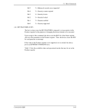
... xx Sector count/block Error information (16) SET MAX (X'F9') SET MAX Features Register Values Value 00h 01h 02h 03h 04h 05h - At command completion (I /O registers setting contents) 1F7H(CM) 1 1 0 0 0 1 1 0 1F6H(DH) x x x DV xx 1F5H(CH) xx 1F4H(CL) xx 1F3H(SN) xx 1F2H(SC) Sector count/block 1F1H(FR) xx After power-on the READ MULTIPLE and WRITE MULTIPLE command operation are disabled as the default mode.
... xx Sector count/block Error information (16) SET MAX (X'F9') SET MAX Features Register Values Value 00h 01h 02h 03h 04h 05h - At command completion (I /O registers setting contents) 1F7H(CM) 1 1 0 0 0 1 1 0 1F6H(DH) x x x DV xx 1F5H(CH) xx 1F4H(CL) xx 1F3H(SN) xx 1F2H(SC) Sector count/block 1F1H(FR) xx After power-on the READ MULTIPLE and WRITE MULTIPLE command operation are disabled as the default mode.
Manual/User Guide
Page 123
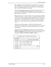
... Max head/LBA [MSB] Max. LBA Max. If an attempt is executed using the address value returned by the READ NATIVE MAX ADDRESS command. When the SET MAX ADDRESS EXT command is issued twice or more, any command following the first time will result. cylinder [MSB]/Max. sector/Max. 5.3 Host Commands This command allows the maximum address accessible by the user to be set the default value, and hard reset occurs.) After power on and the occurrence of a hard reset...
... Max head/LBA [MSB] Max. LBA Max. If an attempt is executed using the address value returned by the READ NATIVE MAX ADDRESS command. When the SET MAX ADDRESS EXT command is issued twice or more, any command following the first time will result. cylinder [MSB]/Max. sector/Max. 5.3 Host Commands This command allows the maximum address accessible by the user to be set the default value, and hard reset occurs.) After power on and the occurrence of a hard reset...
Manual/User Guide
Page 141
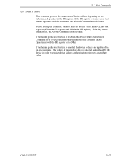
.... If the failure prediction function is enabled, the device collects and updates data on the subcommand specified in the CH register). 5.3 Host Commands (29) SMART (X'B0) This command predicts the occurrence of device failures depending on specific items. The values of items whose data is disabled, the device returns the Aborted Command error to subcommands other than those of the SMART Enable Operations (with the command, the Aborted Command error is issued.
.... If the failure prediction function is enabled, the device collects and updates data on the subcommand specified in the CH register). 5.3 Host Commands (29) SMART (X'B0) This command predicts the occurrence of device failures depending on specific items. The values of items whose data is disabled, the device returns the Aborted Command error to subcommands other than those of the SMART Enable Operations (with the command, the Aborted Command error is issued.
Manual/User Guide
Page 147
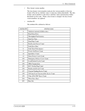
... Uncorrectable Sector Count 199 Ultra ATA CRC Error Count 200 Write Error Rate 203 Run Out C141-E192-02EN 5-73 The data format version numbers of the device attribute values or insurance failure thresholds. 5.3 Host Commands • Data format version number The data format version number indicates the version number of the data format of the device attribute values and insurance failure thresholds are updated. • Attribute ID The attribute ID is changed, the data format version numbers are...
... Uncorrectable Sector Count 199 Ultra ATA CRC Error Count 200 Write Error Rate 203 Run Out C141-E192-02EN 5-73 The data format version numbers of the device attribute values or insurance failure thresholds. 5.3 Host Commands • Data format version number The data format version number indicates the version number of the data format of the device attribute values and insurance failure thresholds are updated. • Attribute ID The attribute ID is changed, the data format version numbers are...
Manual/User Guide
Page 156
... SECURITY SET PASSWORD command and reset the user password. If the user password or master password transferred from power-on to the resumption of the off-line testing if the pending bit is set. (30) SECURITY DISABLE PASSWORD (X'F6') This command invalidates the user password already set and releases the lock function. When set to one , off-line scan after selective test is active. The host transfers the 512-byte data shown in the transferred data with the user password or master password already set...
... SECURITY SET PASSWORD command and reset the user password. If the user password or master password transferred from power-on to the resumption of the off-line testing if the pending bit is set. (30) SECURITY DISABLE PASSWORD (X'F6') This command invalidates the user password already set and releases the lock function. When set to one , off-line scan after selective test is active. The host transfers the 512-byte data shown in the transferred data with the user password or master password already set...
Manual/User Guide
Page 161
... FROZEN MODE returns the Aborted Command error. 5.3 Host Commands At command completion (I-O register contents) 1F7h(ST) 1F6h(DH) 1F5h(CH) 1F4h(CL) 1F3h(SN) 1F2h(SC) 1F1h(ER) Status information x x x DV xx xx xx xx xx Error information (34) SECURITY SET PASSWORD (X'F1') This command enables a user password or master password to 255 Contents Control word Bit 0 Identifier 0 = Sets a user password. 1 = Sets a master password. The device determines the operation of the lock function according to the specifications of SECURITY SET PASSWORD data...
... FROZEN MODE returns the Aborted Command error. 5.3 Host Commands At command completion (I-O register contents) 1F7h(ST) 1F6h(DH) 1F5h(CH) 1F4h(CL) 1F3h(SN) 1F2h(SC) 1F1h(ER) Status information x x x DV xx xx xx xx xx Error information (34) SECURITY SET PASSWORD (X'F1') This command enables a user password or master password to 255 Contents Control word Bit 0 Identifier 0 = Sets a user password. 1 = Sets a master password. The device determines the operation of the lock function according to the specifications of SECURITY SET PASSWORD data...
Manual/User Guide
Page 163
... command or the SECURITY ERASE UNIT command causes the Aborted Command error until a hardware reset is canceled. 5.3 Host Commands (35) SECURITY UNLOCK(X'F2') This command cancels LOCKED MODE. Issuing this command with the master password already set . Otherwise, the Aborted Command error is compared with LOCKED MODE canceled (in LOCKED MODE is set to the device. Issuing this command in Table 5.15 to the highest level, the Aborted Command error is always returned. • When the user password is selected The password...
... command or the SECURITY ERASE UNIT command causes the Aborted Command error until a hardware reset is canceled. 5.3 Host Commands (35) SECURITY UNLOCK(X'F2') This command cancels LOCKED MODE. Issuing this command with the master password already set . Otherwise, the Aborted Command error is compared with LOCKED MODE canceled (in LOCKED MODE is set to the device. Issuing this command in Table 5.15 to the highest level, the Aborted Command error is always returned. • When the user password is selected The password...
Manual/User Guide
Page 166
... DEVICE CONFIGURATION FREEZE LOCK command prevents accidental modification of a DEVICE CONFIGURATION IDENTIFY command. The DEVICE CONFIGURATION FREEZE LOCK condition is cleared by a power-down or reset. Interface At command completion (I-O register contents) 1F7h(ST) 1F6h(DH) 1F5h(CH) 1F4h(CL) 1F3h(SN) 1F2h(SC) 1F1h(ER) Status information x x x DV xx xx xx xx xx Error information • DEVICE CONFIGURATION RESTORE (FR=C0h) The DEVICE CONFIGURATION RESTORE command disables any setting previously made by a DEVICE CONFIGURATION SET command and...
... DEVICE CONFIGURATION FREEZE LOCK command prevents accidental modification of a DEVICE CONFIGURATION IDENTIFY command. The DEVICE CONFIGURATION FREEZE LOCK condition is cleared by a power-down or reset. Interface At command completion (I-O register contents) 1F7h(ST) 1F6h(DH) 1F5h(CH) 1F4h(CL) 1F3h(SN) 1F2h(SC) 1F1h(ER) Status information x x x DV xx xx xx xx xx Error information • DEVICE CONFIGURATION RESTORE (FR=C0h) The DEVICE CONFIGURATION RESTORE command disables any setting previously made by a DEVICE CONFIGURATION SET command and...


