
Manual/User Guide
Page 3
Change of the order No. Revision History Edition 01 02 Date Revised section (*1) (Added/Deleted/Altered) 2003-06-20 2003-10-28 Table 1.2 (Altered) Table 1.5 (Altered) (1/1) Details Change of the acoustic noise specification *1 Section(s) with asterisk (*) refer to the previous edition when those were deleted. C141-E195-02EN
Change of the order No. Revision History Edition 01 02 Date Revised section (*1) (Added/Deleted/Altered) 2003-06-20 2003-10-28 Table 1.2 (Altered) Table 1.5 (Altered) (1/1) Details Change of the acoustic noise specification *1 Section(s) with asterisk (*) refer to the previous edition when those were deleted. C141-E195-02EN
Manual/User Guide
Page 5
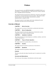
... explains in this manual. CHAPTER 5 Interface This chapter describes the interface specifications of the disk drive. Acronyms and Abbreviations This section gives the meanings of seven chapters and sections explaining the special terminology and abbreviations... that need to be understood to incorporate the drives into user systems. This manual assumes that the reader has a basic knowledge of hard disk drives and their features. Preface This manual describes about MHT2080AH/MHT2060AH/MHT2040AH out of the disk drive and describes their implementations in computer systems. This...
... explains in this manual. CHAPTER 5 Interface This chapter describes the interface specifications of the disk drive. Acronyms and Abbreviations This section gives the meanings of seven chapters and sections explaining the special terminology and abbreviations... that need to be understood to incorporate the drives into user systems. This manual assumes that the reader has a basic knowledge of hard disk drives and their features. Preface This manual describes about MHT2080AH/MHT2060AH/MHT2040AH out of the disk drive and describes their implementations in computer systems. This...
Manual/User Guide
Page 14
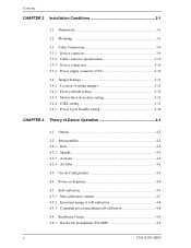
Contents CHAPTER 3 Installation Conditions 3-1 3.1 Dimensions 3-2 3.2 Mounting 3-3 3.3 Cable Connections 3-9 3.3.1 Device connector 3-9 3.3.2 Cable connector specifications 3-10 3.3.3 Device connection 3-10 3.3.4 Power supply connector (CN1 3-10 3.4 Jumper Settings 3-11 3.4.1 Location of setting jumpers 3-11 3.4.2 Factory default setting 3-12 3.4.3 Master drive-slave drive setting 3-12 3.4.4 CSEL setting 3-13 3.4.5 Power Up in Standby setting 3-14 CHAPTER 4 Theory of Device Operation...
Contents CHAPTER 3 Installation Conditions 3-1 3.1 Dimensions 3-2 3.2 Mounting 3-3 3.3 Cable Connections 3-9 3.3.1 Device connector 3-9 3.3.2 Cable connector specifications 3-10 3.3.3 Device connection 3-10 3.3.4 Power supply connector (CN1 3-10 3.4 Jumper Settings 3-11 3.4.1 Location of setting jumpers 3-11 3.4.2 Factory default setting 3-12 3.4.3 Master drive-slave drive setting 3-12 3.4.4 CSEL setting 3-13 3.4.5 Power Up in Standby setting 3-14 CHAPTER 4 Theory of Device Operation...

Manual/User Guide
Page 20
Contents Tables Table 1.1 Table 1.2 Table 1.3 Table 1.4 Table 1.5 Table 1.6 Specifications 1-4 Model names and product numbers 1-5 Current and power dissipation 1-7 Environmental specifications 1-8 Acoustic noise specification 1-9 Shock and vibration specification 1-9 Table 3.1 Surface temperature measurement points and standard values...........3-6 Table 3.2 Cable connector specifications 3-10 Table 5.1 Signal assignment on the interface connector 5-3 Table 5.2 I/O registers 5-7 Table 5.3 Command code and parameters 5-15 Table...
Contents Tables Table 1.1 Table 1.2 Table 1.3 Table 1.4 Table 1.5 Table 1.6 Specifications 1-4 Model names and product numbers 1-5 Current and power dissipation 1-7 Environmental specifications 1-8 Acoustic noise specification 1-9 Shock and vibration specification 1-9 Table 3.1 Surface temperature measurement points and standard values...........3-6 Table 3.2 Cable connector specifications 3-10 Table 5.1 Signal assignment on the interface connector 5-3 Table 5.2 I/O registers 5-7 Table 5.3 Command code and parameters 5-15 Table...
Manual/User Guide
Page 21
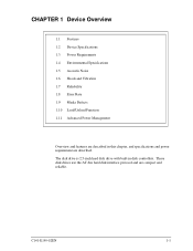
The disk drive is 2.5-inch hard disk drive with built-in this chapter, and specifications and power requirement are described. These disk drives use the AT-bus hard disk interface protocol and are compact and reliable. CHAPTER 1 Device Overview 1.1 Features 1.2 Device Specifications 1.3 Power Requirements 1.4 Environmental Specifications 1.5 Acoustic Noise 1.6 Shock and Vibration 1.7 Reliability 1.8 Error Rate 1.9 Media Defects 1.10 Load/Unload Function 1.11 Advanced Power Management Overview and features are described in disk controllers. C141-E195-02EN 1-1
The disk drive is 2.5-inch hard disk drive with built-in this chapter, and specifications and power requirement are described. These disk drives use the AT-bus hard disk interface protocol and are compact and reliable. CHAPTER 1 Device Overview 1.1 Features 1.2 Device Specifications 1.3 Power Requirements 1.4 Environmental Specifications 1.5 Acoustic Noise 1.6 Shock and Vibration 1.7 Reliability 1.8 Error Rate 1.9 Media Defects 1.10 Load/Unload Function 1.11 Advanced Power Management Overview and features are described in disk controllers. C141-E195-02EN 1-1

Manual/User Guide
Page 24
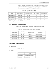
MHT2080AH 80 GB 156,301,488 MHT2060AH 60 GB 117,210,240 512 5,400 rpm ± 1% 5.56 ms MHT2040AH 40 GB 78,140,160 1.5 ms (typ.) Read: 12ms (typ.) 22 ms (typ.) 4.0 sec (typ.) ATA-6 (Max. Device Overview 1.2 Device Specifications 1.2.1 Specifications summary Table 1.1 shows the specifications...Data Buffer Size Physical Dimensions (Height × Width × Depth) Weight *1: Capacity under the LBA mode. Table 1.1 Specifications (1/2) Format Capacity (*1) Number of the disk drives. Cable length: 18inches (0.46 m)) (equipped with expansion function) 55.4 MB/s Max. 100 MB/s Max (U-DMA mode5)...
MHT2080AH 80 GB 156,301,488 MHT2060AH 60 GB 117,210,240 512 5,400 rpm ± 1% 5.56 ms MHT2040AH 40 GB 78,140,160 1.5 ms (typ.) Read: 12ms (typ.) 22 ms (typ.) 4.0 sec (typ.) ATA-6 (Max. Device Overview 1.2 Device Specifications 1.2.1 Specifications summary Table 1.1 shows the specifications...Data Buffer Size Physical Dimensions (Height × Width × Depth) Weight *1: Capacity under the LBA mode. Table 1.1 Specifications (1/2) Format Capacity (*1) Number of the disk drives. Cable length: 18inches (0.46 m)) (equipped with expansion function) 55.4 MB/s Max. 100 MB/s Max (U-DMA mode5)...
Manual/User Guide
Page 25
...• +5V ±5% (2) Ripple Maximum Frequency +5 V 100 mV (peak to peak) DC to 1 MHz C141-E195-02EN 1-5 of Cylinder MHT2080AH 8.45 GB 16,383 MHT2060AH 8.45 GB 16,383 MHT2040AH 8.45 GB 16,383 *1 On using for which the CHS mode has been selected using... the formatted capacity, number of logical cylinders, number of heads, and number of sectors of the disk drive. Table 1.2 Model names and product numbers Model Name MHT2080AH MHT2060AH MHT2040AH Capacity (user area) 80 GB 60 GB 40 GB Mounting screw Order No. Table 1.1 Specifications (2/2) Model Capacity (*1) No.
...• +5V ±5% (2) Ripple Maximum Frequency +5 V 100 mV (peak to peak) DC to 1 MHz C141-E195-02EN 1-5 of Cylinder MHT2080AH 8.45 GB 16,383 MHT2060AH 8.45 GB 16,383 MHT2040AH 8.45 GB 16,383 *1 On using for which the CHS mode has been selected using... the formatted capacity, number of logical cylinders, number of heads, and number of sectors of the disk drive. Table 1.2 Model names and product numbers Model Name MHT2080AH MHT2060AH MHT2040AH Capacity (user area) 80 GB 60 GB 40 GB Mounting screw Order No. Table 1.1 Specifications (2/2) Model Capacity (*1) No.

Manual/User Guide
Page 28
... Thermal Gradient Humidity • Operating • Non-operating • Maximum Wet Bulb Altitude (relative to sea level) • Operating • Non-operating Specification 5 °C to 55 °C (ambient) 5 °C to 60 °C (disk enclosure surface) -40 °C to 65 °C 20 ...;C (Non-operating) -300 to 3,000 m -300 to be concerned with the power on /off sequence. 1.4 Environmental Specifications Table 1.4 lists the environmental specifications. Device Overview Figure 1.2 Current fluctuation (Typ.) at +5 V when power is abnormal. These prevent data from being destroyed and...
... Thermal Gradient Humidity • Operating • Non-operating • Maximum Wet Bulb Altitude (relative to sea level) • Operating • Non-operating Specification 5 °C to 55 °C (ambient) 5 °C to 60 °C (disk enclosure surface) -40 °C to 65 °C 20 ...;C (Non-operating) -300 to 3,000 m -300 to be concerned with the power on /off sequence. 1.4 Environmental Specifications Table 1.4 lists the environmental specifications. Device Overview Figure 1.2 Current fluctuation (Typ.) at +5 V when power is abnormal. These prevent data from being destroyed and...

Manual/User Guide
Page 29
... specification Item Specification (typ.) • Idle mode (DRIVE READY) 2.2 B [MHT2040AH] Sound Power 2.8 B [MHT2080AH/MHT2060AH/MHT2040AH (*1)] Sound Pressure (at 0.3m) 25 dB(A) [MHT2040AH] 34 dB(A) [MHT2080AH/MHT2060AH/MHT2040AH (*1)] * 1 In case of model "CA06377-B034". 1.6 Shock and Vibration Table 1.6 lists the shock and vibration specification. Table 1.6 Shock and vibration specification Item Specification Vibration...120G 0-peak) 11ms duration (no damage) C141-E195-02EN 1-9 1.5 Acoustic Noise 1.5 Acoustic Noise Table 1.5 lists the acoustic noise specification.
... specification Item Specification (typ.) • Idle mode (DRIVE READY) 2.2 B [MHT2040AH] Sound Power 2.8 B [MHT2080AH/MHT2060AH/MHT2040AH (*1)] Sound Pressure (at 0.3m) 25 dB(A) [MHT2040AH] 34 dB(A) [MHT2080AH/MHT2060AH/MHT2040AH (*1)] * 1 In case of model "CA06377-B034". 1.6 Shock and Vibration Table 1.6 lists the shock and vibration specification. Table 1.6 Shock and vibration specification Item Specification Vibration...120G 0-peak) 11ms duration (no damage) C141-E195-02EN 1-9 1.5 Acoustic Noise 1.5 Acoustic Noise Table 1.5 lists the acoustic noise specification.

Manual/User Guide
Page 42
... attached. (3) Limitation of mounting Note) These dimensions are recommended values; IMPORTANT Use M3 screw for the mounting screw and the screw length should satisfy the specification in Figure 3.3. The tightening torque must be 0.49N·m (5kgf·cm). Bottom surface mounting DE 2 A Frame of system cabinet 2.5 2.5 2.5 Side surface 2.5 mounting PCA B Frame...
... attached. (3) Limitation of mounting Note) These dimensions are recommended values; IMPORTANT Use M3 screw for the mounting screw and the screw length should satisfy the specification in Figure 3.3. The tightening torque must be 0.49N·m (5kgf·cm). Bottom surface mounting DE 2 A Frame of system cabinet 2.5 2.5 2.5 Side surface 2.5 mounting PCA B Frame...

Manual/User Guide
Page 48
...-cable Disk Drive #0 ATA-cable DC Power supply Power supply cable Disk Drive #1 Figure 3.9 Cable connections 3.3.4 Power supply connector (CN1) Figure 3.10 shows the pin assignment of the power supply connector (CN1). 3-10 C141-E195-02EN Table 3.2 Cable connector specifications ATA interface... FCI IMPORTANT For the host interface cable, use a ribbon cable. Installation Conditions 3.3.2 Cable connector specifications Table 3.2 lists the recommended specifications for cables carrying differential signals. 3.3.3 Device connection Figure 3.9 shows how to connect the devices.
...-cable Disk Drive #0 ATA-cable DC Power supply Power supply cable Disk Drive #1 Figure 3.9 Cable connections 3.3.4 Power supply connector (CN1) Figure 3.10 shows the pin assignment of the power supply connector (CN1). 3-10 C141-E195-02EN Table 3.2 Cable connector specifications ATA interface... FCI IMPORTANT For the host interface cable, use a ribbon cable. Installation Conditions 3.3.2 Cable connector specifications Table 3.2 lists the recommended specifications for cables carrying differential signals. 3.3.3 Device connection Figure 3.9 shows how to connect the devices.
Manual/User Guide
Page 70
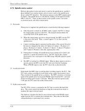
...rotating in the SVC that is used for this hard disk drive. When no phase signal is sent for speed detection. When the rotational speed reaches 5,400 rpm, the SVC enters the stable rotation mode. ... that , repeating this counter electromotive force and reports to the MPU using a PHASE signal for a specific period, the MPU resets the SVC and starts from the beginning. When a PHASE signal is sent...the spindle motor. The SVC detects this order). The SVC starts a phase switching by Fujitsu. The spindle motor is controlled by sending several signals from the MPU to maintain the target...
...rotating in the SVC that is used for this hard disk drive. When no phase signal is sent for speed detection. When the rotational speed reaches 5,400 rpm, the SVC enters the stable rotation mode. ... that , repeating this counter electromotive force and reports to the MPU using a PHASE signal for a specific period, the MPU resets the SVC and starts from the beginning. When a PHASE signal is sent...the spindle motor. The SVC detects this order). The SVC starts a phase switching by Fujitsu. The spindle motor is controlled by sending several signals from the MPU to maintain the target...

Manual/User Guide
Page 79
... selects the slave device, the diagnostic code of remaining sectors that the command is , this register is posted. (3) Features register (X'1F1') The Features register provides specific feature to X'06'). With the EXT system command, the sector count is 65536 when value of this register indicates the number of the slave device...
... selects the slave device, the diagnostic code of remaining sectors that the command is , this register is posted. (3) Features register (X'1F1') The Features register provides specific feature to X'06'). With the EXT system command, the sector count is 65536 when value of this register indicates the number of the slave device...

Manual/User Guide
Page 101
... the number of sectors per track and the maximum head number (maximum head number is "number of heads minus 1") per cylinder with only CHS mode specification. Other than X'00' is posted. Upon receipt of this command, the device sets the BSY bit of Status register and saves the parameters. Then the... regardless of the setting of disabling the reverting to X'00', an ABORTED COMMAND error is specified, this command terminates normally. The device ignores the L bit specification and operates with this command. C141-E195-02EN 5-31
... the number of sectors per track and the maximum head number (maximum head number is "number of heads minus 1") per cylinder with only CHS mode specification. Other than X'00' is posted. Upon receipt of this command, the device sets the BSY bit of Status register and saves the parameters. Then the... regardless of the setting of disabling the reverting to X'00', an ABORTED COMMAND error is specified, this command terminates normally. The device ignores the L bit specification and operates with this command. C141-E195-02EN 5-31

Manual/User Guide
Page 116
The Mode-2 level requires the longest shifting time, depending on or a hardware reset occurs for a specific time. Low Power Idle: The spindle motor rotates, and the head is unloaded. 5-46 C141-E195-02EN The settings of the APM level revert to ... which the power management level shifts is from Active Idle to Low Power Idle to the Mode-1 when power-on the APM level settings. The drive automatically shifts to power saving mode up to the specified APM level when the...
The Mode-2 level requires the longest shifting time, depending on or a hardware reset occurs for a specific time. Low Power Idle: The spindle motor rotates, and the head is unloaded. 5-46 C141-E195-02EN The settings of the APM level revert to ... which the power management level shifts is from Active Idle to Low Power Idle to the Mode-1 when power-on the APM level settings. The drive automatically shifts to power saving mode up to the specified APM level when the...
Manual/User Guide
Page 137
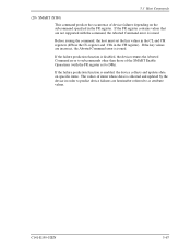
... (4Fh in the CL register and C2h in the FR register. If the failure prediction function is enabled, the device collects and updates data on specific items. The values of device failures depending on the subcommand specified in the CH register).
... (4Fh in the CL register and C2h in the FR register. If the failure prediction function is enabled, the device collects and updates data on specific items. The values of device failures depending on the subcommand specified in the CH register).

Manual/User Guide
Page 140
...SMART Enable-Disable Attribute AutoSave subcommand (FR register = D2h) to any command from the host computer. This setting is preserved whether the drive's power is performed without relation to use a feature which regularly save the device attribute value data on a medium. Then the device ...attribute values with insurance failure threshold values. The host can predict failures in the enabled (when the SC register specification ≠ 00h) or disabled (when the SC register specification = 00) state. If an attribute value is below the insurance failure threshold value, the device is about...
...SMART Enable-Disable Attribute AutoSave subcommand (FR register = D2h) to any command from the host computer. This setting is preserved whether the drive's power is performed without relation to use a feature which regularly save the device attribute value data on a medium. Then the device ...attribute values with insurance failure threshold values. The host can predict failures in the enabled (when the SC register specification ≠ 00h) or disabled (when the SC register specification = 00) state. If an attribute value is below the insurance failure threshold value, the device is about...

Manual/User Guide
Page 152
... command and reset the user password. Interface Bit 0 1 2 3 4 5...15 Table 5.14 Selective self-test feature flags Description Vendor specific (unused) When set to one, perform off-line scan after selective test Vendor specific (unused) When set to one , off-line scan after selective test is pending. If the user password or master...
... command and reset the user password. Interface Bit 0 1 2 3 4 5...15 Table 5.14 Selective self-test feature flags Description Vendor specific (unused) When set to one, perform off-line scan after selective test Vendor specific (unused) When set to one , off-line scan after selective test is pending. If the user password or master...

Manual/User Guide
Page 157
... to 255 Contents Control word Bit 0 Identifier 0 = Sets a user password. 1 = Sets a master password. The device determines the operation of the lock function according to the specifications of SECURITY SET PASSWORD data Word 0 1 to 16 17 18 to be set.
... to 255 Contents Control word Bit 0 Identifier 0 = Sets a user password. 1 = Sets a master password. The device determines the operation of the lock function according to the specifications of SECURITY SET PASSWORD data Word 0 1 to 16 17 18 to be set.

Manual/User Guide
Page 166
... ADDRESS (EXT) command is issued twice or more in LBA mode. Interface (39) SET MAX ADDRESS EXT (37H): Option (customizing) • Description This command limits specifications so that the highest address that is outside of the IDENTIFY DEVICE command response. If read or write processing is executed for an address that...
... ADDRESS (EXT) command is issued twice or more in LBA mode. Interface (39) SET MAX ADDRESS EXT (37H): Option (customizing) • Description This command limits specifications so that the highest address that is outside of the IDENTIFY DEVICE command response. If read or write processing is executed for an address that...
