Manual/User Guide
Page 4
ii C141-E166 Related Standards Product specifications and functions described in this manual takes precedence. Document number T10/1236D Rev.20 [NCITS.351:2001] T10/996D Rev.8c [NCITS.306:1998] T10/1157D Rev.20 T10/1365D Rev.7 Title SCSI Primary Commands-2 (SPC-2) SCSI-3 Block Commands (SBC) SCSI Architecture Model-2 (SAM-2) SCSI Parallel Interface-4 (SPI-4) *1 ANSI = American National Standard Institute In case of conflict between this manual and any referenced document, this manual comply with the following ANSI (*1) standards.
ii C141-E166 Related Standards Product specifications and functions described in this manual takes precedence. Document number T10/1236D Rev.20 [NCITS.351:2001] T10/996D Rev.8c [NCITS.306:1998] T10/1157D Rev.20 T10/1365D Rev.7 Title SCSI Primary Commands-2 (SPC-2) SCSI-3 Block Commands (SBC) SCSI Architecture Model-2 (SAM-2) SCSI Parallel Interface-4 (SPI-4) *1 ANSI = American National Standard Institute In case of conflict between this manual and any referenced document, this manual comply with the following ANSI (*1) standards.
Manual/User Guide
Page 7
...1. To short the setting terminal, use the short plug attached when the device is on . • Write protect: CN2 9-10 (NP model only) 3. Important Alert Items Important Alert Messages The important alert messages in this section. Damage 5-11 1. Hot temperature To prevent injury, do... not handle the drive until after the device has 5-1 cooled sufficiently after turning off the power. The user must not change the setting of terminals except...
...1. To short the setting terminal, use the short plug attached when the device is on . • Write protect: CN2 9-10 (NP model only) 3. Important Alert Items Important Alert Messages The important alert messages in this section. Damage 5-11 1. Hot temperature To prevent injury, do... not handle the drive until after the device has 5-1 cooled sufficiently after turning off the power. The user must not change the setting of terminals except...
Manual/User Guide
Page 11
... page CHAPTER 1 GENERAL DESCRIPTION 1-1 1.1 Standard Features ...1-2 1.2 Hardware Structure...1-6 1.3 System Configuration ...1-9 CHAPTER 2 SPECIFICATIONS 2-1 2.1 Hardware Specifications...2-1 2.1.1 Model name and order number 2-1 2.1.2 Function specifications...2-2 2.1.3 Environmental specifications 2-4 2.1.4 Error rate ...2-5 2.1.5 Reliability...2-5 2.2 SCSI Function Specifications 2-7 CHAPTER 3 DATA... Mounting ...4-4 4.1.3 Notes on mounting ...4-4 4.2 Power Supply Requirements 4-8 4.3 Connection Requirements 4-11 4.3.1 68 pin connector 16-bit SCSI model (NP model 4-11 C141-E166 ix
... page CHAPTER 1 GENERAL DESCRIPTION 1-1 1.1 Standard Features ...1-2 1.2 Hardware Structure...1-6 1.3 System Configuration ...1-9 CHAPTER 2 SPECIFICATIONS 2-1 2.1 Hardware Specifications...2-1 2.1.1 Model name and order number 2-1 2.1.2 Function specifications...2-2 2.1.3 Environmental specifications 2-4 2.1.4 Error rate ...2-5 2.1.5 Reliability...2-5 2.2 SCSI Function Specifications 2-7 CHAPTER 3 DATA... Mounting ...4-4 4.1.3 Notes on mounting ...4-4 4.2 Power Supply Requirements 4-8 4.3 Connection Requirements 4-11 4.3.1 68 pin connector 16-bit SCSI model (NP model 4-11 C141-E166 ix
Manual/User Guide
Page 12
... Cable connector requirements 4-20 External operator panel (on NP model drives only 4-22 CHAPTER 5 INSTALLATION 5-1 5.1 Notes on Handling Drives 5-1 5.2 Connections...5-3 5.3 Setting Terminals ...5-5 5.3.1 SCSI ID setting (NP model only 5-6 5.3.2 Each mode setting (NP model only 5-7 5.3.3 Mode settings ...5-9 5.4 Mounting Drives...5-10 5.4.1 Check before mounting ...5-10 5.4.2 Mounting procedures...5-10 5.5 Connecting Cables...5-11 5.6 Confirming Operations after Installation and Preparation for...
... Cable connector requirements 4-20 External operator panel (on NP model drives only 4-22 CHAPTER 5 INSTALLATION 5-1 5.1 Notes on Handling Drives 5-1 5.2 Connections...5-3 5.3 Setting Terminals ...5-5 5.3.1 SCSI ID setting (NP model only 5-6 5.3.2 Each mode setting (NP model only 5-7 5.3.3 Mode settings ...5-9 5.4 Mounting Drives...5-10 5.4.1 Check before mounting ...5-10 5.4.2 Mounting procedures...5-10 5.5 Connecting Cables...5-11 5.6 Confirming Operations after Installation and Preparation for...
Manual/User Guide
Page 13
...6.4.2 6.4.3 6.4.4 6.4.5 Diagnostic test ...6-12 Troubleshooting Procedures 6-13 Outline of troubleshooting procedures 6-13 Troubleshooting with disk drive replacement in the field 6-13 Troubleshooting at the repair site 6-15 Troubleshooting with parts replacement in the factory ...), (B-47-xx), (B-49-00), (B-4D-xx) and (B-4E-00): SCSI interface error 7-4 APPENDIX A SETTING TERMINALS A-1 A.1 Setting Terminals (on NP model only A-2 APPENDIX B CONNECTOR SIGNAL ALLOCATION B-1 B.1 SCSI Connector Signal Allocation: 68 pin type LVD 16-bit SCSI B-2 B.2 SCSI Connector Signal Allocation: SCA2 ...
...6.4.2 6.4.3 6.4.4 6.4.5 Diagnostic test ...6-12 Troubleshooting Procedures 6-13 Outline of troubleshooting procedures 6-13 Troubleshooting with disk drive replacement in the field 6-13 Troubleshooting at the repair site 6-15 Troubleshooting with parts replacement in the factory ...), (B-47-xx), (B-49-00), (B-4D-xx) and (B-4E-00): SCSI interface error 7-4 APPENDIX A SETTING TERMINALS A-1 A.1 Setting Terminals (on NP model only A-2 APPENDIX B CONNECTOR SIGNAL ALLOCATION B-1 B.1 SCSI Connector Signal Allocation: 68 pin type LVD 16-bit SCSI B-2 B.2 SCSI Connector Signal Allocation: SCA2 ...
Manual/User Guide
Page 15
FIGURES Figure 1.1 Figure 1.2 Figure 1.3 Figure 1.4 page NC model drives outer view 1-6 NP model drives outer view 1-6 Disk/head configuration...1-7 System configuration ...1-9 Figure 3.1 Figure 3.2 Figure 3.3 Figure 3.4 Figure 3.5 Figure 3.6 Figure 3.7 Figure 3.8 Cylinder configuration...3-2 Spare area... filter (recommended 4-11 NP connectors and terminals location 4-11 16-bit SCSI interface connector 4-12 Power supply connector (16-bit SCSI model 4-12 External operator panel connector (CN1 4-13 External operator panel connector (CN2 4-14 16-bit SCSI ID external input 4-15 Output...
FIGURES Figure 1.1 Figure 1.2 Figure 1.3 Figure 1.4 page NC model drives outer view 1-6 NP model drives outer view 1-6 Disk/head configuration...1-7 System configuration ...1-9 Figure 3.1 Figure 3.2 Figure 3.3 Figure 3.4 Figure 3.5 Figure 3.6 Figure 3.7 Figure 3.8 Cylinder configuration...3-2 Spare area... filter (recommended 4-11 NP connectors and terminals location 4-11 16-bit SCSI interface connector 4-12 Power supply connector (16-bit SCSI model 4-12 External operator panel connector (CN1 4-13 External operator panel connector (CN2 4-14 16-bit SCSI ID external input 4-15 Output...
Manual/User Guide
Page 16
... SCSI connector 4-20 External operator panel circuit example 4-22 Figure 5.1 Figure 5.2 Figure 5.3 Figure 5.4 Figure 5.5 SCSI bus connections ...5-4 Setting terminals location (on NP models only 5-5 CN2 setting terminal (on NP models only 5-6 Checking the SCSI connection (A 5-14 Checking the SCSI connection (B 5-15 Figure 6.1 Figure 6.2 Figure 6.3 Revision label ...6-9 Indicating revision numbers 6-10 Test flowchart...
... SCSI connector 4-20 External operator panel circuit example 4-22 Figure 5.1 Figure 5.2 Figure 5.3 Figure 5.4 Figure 5.5 SCSI bus connections ...5-4 Setting terminals location (on NP models only 5-5 CN2 setting terminal (on NP models only 5-6 Checking the SCSI connection (A 5-14 Checking the SCSI connection (B 5-15 Figure 6.1 Figure 6.2 Figure 6.3 Revision label ...6-9 Indicating revision numbers 6-10 Test flowchart...
Manual/User Guide
Page 17
... mode settings (by CHANGE DEFINITION command 5-9 Table 5.8 Setting check list (NP model only 5-10 Table 6.1 Self-diagnostic functions ...6-1 Table 6.2 System-level field troubleshooting 6-14 Table 6.3 Disk drive troubleshooting ...6-15 Table 7.1 Definition of sense data ...7-3 Table A.1 CN2 setting terminal (on NP model drives only A-2 Table B.1 SCSI connector (68 pin type LVD 16-bit SCSI): CN1...
... mode settings (by CHANGE DEFINITION command 5-9 Table 5.8 Setting check list (NP model only 5-10 Table 6.1 Self-diagnostic functions ...6-1 Table 6.2 System-level field troubleshooting 6-14 Table 6.3 Disk drive troubleshooting ...6-15 Table 7.1 Definition of sense data ...7-3 Table A.1 CN2 setting terminal (on NP model drives only A-2 Table B.1 SCSI connector (68 pin type LVD 16-bit SCSI): CN1...
Manual/User Guide
Page 20
... of connectable SCSI devices on the same SCSI bus is varied as follows. • 8-bit SCSI: 8 drives max. (option for NP model) • 16-bit SCSI: 16 drives max. (4) High speed data transfer Such a high data transfer rate on the SCSI bus can be connected directly to accommodate future ... bus is 40 MB/s maximum at the paced transfer synchronous mode. 1-2 C141-E166 This allows software to the SCSI bus of the disk drive. The IDD can manipulate data through logical block addressing regardless of the physical characteristics of the host system. (2) SCSI standard The IDD provides ...
... of connectable SCSI devices on the same SCSI bus is varied as follows. • 8-bit SCSI: 8 drives max. (option for NP model) • 16-bit SCSI: 16 drives max. (4) High speed data transfer Such a high data transfer rate on the SCSI bus can be connected directly to accommodate future ... bus is 40 MB/s maximum at the paced transfer synchronous mode. 1-2 C141-E166 This allows software to the SCSI bus of the disk drive. The IDD can manipulate data through logical block addressing regardless of the physical characteristics of the host system. (2) SCSI standard The IDD provides ...
Manual/User Guide
Page 24
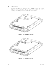
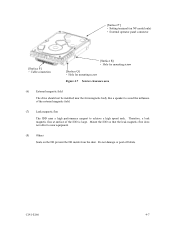
Figure 1.1 NC model drives outer view Figure 1.2 NP model drives outer view 1-6 C141-E166 1.2 Hardware Structure An outer view of the IDD is composed of the disk, head, spindle motor, mounted disk enclosure (DE) with actuator and air circulation filter, as well as read/write pre-amp with the printed circuit assembly (PCA) of the controller. The IDD is given in Figures 1.1 and 1.2.
Figure 1.1 NC model drives outer view Figure 1.2 NP model drives outer view 1-6 C141-E166 1.2 Hardware Structure An outer view of the IDD is composed of the disk, head, spindle motor, mounted disk enclosure (DE) with actuator and air circulation filter, as well as read/write pre-amp with the printed circuit assembly (PCA) of the controller. The IDD is given in Figures 1.1 and 1.2.
Manual/User Guide
Page 25
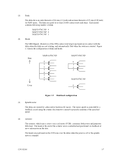
...configuration of 25 mm (0.98 inch) for at the end of the actuator arm is stopped. The motor speed is controlled by a direct-drive hall-less DC motor. MAP3147NC/NP: 4 MAP3735NC/NP: 2 MAP3367NC/NP: 1 (2) Heads The MR (Magnet - Resistive) of the specified speed. (4) Actuator The ...actuator, which uses a rotary voice coil motor (VCM), consumes little power and generates little heat. C141-E166 1-7 Each model contains following number of ...
...configuration of 25 mm (0.98 inch) for at the end of the actuator arm is stopped. The motor speed is controlled by a direct-drive hall-less DC motor. MAP3147NC/NP: 4 MAP3735NC/NP: 2 MAP3367NC/NP: 1 (2) Heads The MR (Magnet - Resistive) of the specified speed. (4) Actuator The ...actuator, which uses a rotary voice coil motor (VCM), consumes little power and generates little heat. C141-E166 1-7 Each model contains following number of ...
Manual/User Guide
Page 28
The initiator selects one SCSI device by specifying that the whole volume of disk drive is possible on multi-SCSI devices. (2) Addressing of SCSI ID and LUN are as follows: • SCSI ID: • LUN: 8-bit SCSI:Selectable from 0 to ... Figure 1.4). For example, the system can be configured as multi-host system on which multiple host computers that operates as target is assigned for NP model, switch selectable) 16-bit SCSI:Selectable from 0 to the SCSI bus that operate as initiator or connected through the SCSI bus.
The initiator selects one SCSI device by specifying that the whole volume of disk drive is possible on multi-SCSI devices. (2) Addressing of SCSI ID and LUN are as follows: • SCSI ID: • LUN: 8-bit SCSI:Selectable from 0 to ... Figure 1.4). For example, the system can be configured as multi-host system on which multiple host computers that operates as target is assigned for NP model, switch selectable) 16-bit SCSI:Selectable from 0 to the SCSI bus that operate as initiator or connected through the SCSI bus.
Manual/User Guide
Page 29
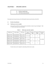
....01 GB 4 8 73.50 GB 2 4 #6-32UNC 36.74 GB 1 2 The data format can be changed by reinitializing with the user's system. Table 2.1 Model names and order numbers Model name MAP3147NC MAP3147NP MAP3735NC MAP3735NP MAP3367NC MAP3367NP Order number CA06200-B400 CA06200-B460 CA06200-B200 CA06200-B260 CA06200-B100 CA06200-B160 SCSI type SCA2, LVD...
....01 GB 4 8 73.50 GB 2 4 #6-32UNC 36.74 GB 1 2 The data format can be changed by reinitializing with the user's system. Table 2.1 Model names and order numbers Model name MAP3147NC MAP3147NP MAP3735NC MAP3735NP MAP3367NC MAP3367NP Order number CA06200-B400 CA06200-B460 CA06200-B200 CA06200-B260 CA06200-B100 CA06200-B160 SCSI type SCA2, LVD...
Manual/User Guide
Page 35
... resistor is mounted on the PCA × TERMPWR signal send function Ο Connector 68 pin P cable connector 80 pin SCA2 connector Ο (NP model) Ο (NC model) Data bus parity (Data bus CRC) Ο Bus arbitration function Ο Disconnection/reconnection function Ο Addressing SCSI ID 16-bit SCSI LUN (logical unit...
... resistor is mounted on the PCA × TERMPWR signal send function Ο Connector 68 pin P cable connector 80 pin SCA2 connector Ο (NP model) Ο (NC model) Data bus parity (Data bus CRC) Ο Bus arbitration function Ο Disconnection/reconnection function Ο Addressing SCSI ID 16-bit SCSI LUN (logical unit...
Manual/User Guide
Page 45
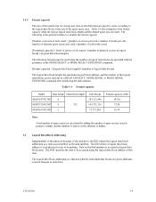
... of alternate spare sectors per cell - Table 3.4 Format capacity Model Data heads Data block length MAP3147NC/NP 8 MAP3735NC/NP 4 512 MAP3367NC/NP 2 User blocks...or MODE SENSE EXTENDED command after initializing the disk medium. The INIT specifies the data to each drive. The IDD relates a logical data block address to be read out by adding the number of...sectors in the alternate cylinders. 3.2 Logical Data Block Addressing Independently of the physical structure of the disk drive, the IDD adopts the logical data block addressing as a data access method on the disk medium....
... of alternate spare sectors per cell - Table 3.4 Format capacity Model Data heads Data block length MAP3147NC/NP 8 MAP3735NC/NP 4 512 MAP3367NC/NP 2 User blocks...or MODE SENSE EXTENDED command after initializing the disk medium. The INIT specifies the data to each drive. The IDD relates a logical data block address to be read out by adding the number of...sectors in the alternate cylinders. 3.2 Logical Data Block Addressing Independently of the physical structure of the disk drive, the IDD adopts the logical data block addressing as a data access method on the disk medium....
Manual/User Guide
Page 59
[Surface P'] • Setting terminal (on NP model only) • External operator panel connector [Surface P] • Cable connection [Surface R] • Hole for mounting screw [Surface Q] • Hole for mounting screw Figure 4.7 Service clearance area (6) External magnetic field The drive should not be installed near equipment. (8) Others Seals on the DE prevent the DE inside...
[Surface P'] • Setting terminal (on NP model only) • External operator panel connector [Surface P] • Cable connection [Surface R] • Hole for mounting screw [Surface Q] • Hole for mounting screw Figure 4.7 Service clearance area (6) External magnetic field The drive should not be installed near equipment. (8) Others Seals on the DE prevent the DE inside...
Manual/User Guide
Page 62
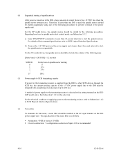
...to set a spindle motor start the spindle motors. Therefore, if more than 12-second intervals to start the spindle motors sequentially. For the NP model drives, the spindle motors should be started by the following time. [Delay time] = [SCSI ID] × 12 seconds SCSI ID 0 1...5.3.2. (4) Sequential starting 0 12 s 24 ...s 180 s (5) Power supply to SCSI terminating resistor If power for this selection. For the NC model drives, the spindle motors should be started sequentially using one IDD is used, the spindle motors should be started after a delay of current flows in...
...to set a spindle motor start the spindle motors. Therefore, if more than 12-second intervals to start the spindle motors sequentially. For the NP model drives, the spindle motors should be started by the following time. [Delay time] = [SCSI ID] × 12 seconds SCSI ID 0 1...5.3.2. (4) Sequential starting 0 12 s 24 ...s 180 s (5) Power supply to SCSI terminating resistor If power for this selection. For the NC model drives, the spindle motors should be started sequentially using one IDD is used, the spindle motors should be started after a delay of current flows in...
Manual/User Guide
Page 63
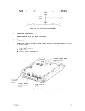
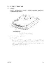
Figure 4.12 AC noise filter (recommended) 4.3 Connection Requirements 4.3.1 68 pin connector 16-bit SCSI model (NP model) (1) Connectors Figures 4.13 show the locations of connectors and terminals on the 68 pin connector type 16-bit SCSI (MP) model. • Power supply connector • SCSI connector • External operator panel connector External operator panel connector (CN2) Power supply connector (CN1) External operator panel connector (CN1) SCSI connector (CN1) Figure 4.13 NP connectors and terminals location C141-E166 4-11
Figure 4.12 AC noise filter (recommended) 4.3 Connection Requirements 4.3.1 68 pin connector 16-bit SCSI model (NP model) (1) Connectors Figures 4.13 show the locations of connectors and terminals on the 68 pin connector type 16-bit SCSI (MP) model. • Power supply connector • SCSI connector • External operator panel connector External operator panel connector (CN2) Power supply connector (CN1) External operator panel connector (CN1) SCSI connector (CN1) Figure 4.13 NP connectors and terminals location C141-E166 4-11
Manual/User Guide
Page 64
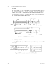
... has two 34-pin rows spaced 1.27 mm (0.05 inch) apart. For details on the SCSI connector. Figure 4.15 Power supply connector (16-bit SCSI model) 4-12 C141-E166 Pin 34 Pin 1 2.00mm Pin A1 Pin 1 2.54mm Pin 68 1.27mm Pin 35 2.00m Pin A2 5.08mm 0.40mm 0.635mm 0.40mm 1.00mm 1.30mm...
... has two 34-pin rows spaced 1.27 mm (0.05 inch) apart. For details on the SCSI connector. Figure 4.15 Power supply connector (16-bit SCSI model) 4-12 C141-E166 Pin 34 Pin 1 2.00mm Pin A1 Pin 1 2.54mm Pin 68 1.27mm Pin 35 2.00m Pin A2 5.08mm 0.40mm 0.635mm 0.40mm 1.00mm 1.30mm...
Manual/User Guide
Page 71
...Section B.2 in SCSI Physical Interface Specifications. For details on the physical/electrical requirements of connectors on the connector. 4.3.2 SCA2 type SCSI model (NC model) (1) Connectors Figure 4.21 shows the locations of the interface signals, refer to SCSI-3 type which has two 40-pin rows spaced ... SCA-2 connector conforming to Sections 1.3 and 1.4 in Appendix B for signal assignments on the SCA2 type SCSI model. SCSI connector (including power supply connector) SCSI connector (CN1) Figure 4.21 NC connectors location (2) SCSI connector and power supply connector a.
...Section B.2 in SCSI Physical Interface Specifications. For details on the physical/electrical requirements of connectors on the connector. 4.3.2 SCA2 type SCSI model (NC model) (1) Connectors Figure 4.21 shows the locations of the interface signals, refer to SCSI-3 type which has two 40-pin rows spaced ... SCA-2 connector conforming to Sections 1.3 and 1.4 in Appendix B for signal assignments on the SCA2 type SCSI model. SCSI connector (including power supply connector) SCSI connector (CN1) Figure 4.21 NC connectors location (2) SCSI connector and power supply connector a.

