Manual/User Guide
Page 12
... initial operations 5-12 5.6.2 Checking SCSI connection 5-13 5.6.3 Formatting ...5-16 5.6.4 Setting parameters ...5-18 5.7 Dismounting Drives...5-22 5.8 Spare Disk Drive ...5-22 CHAPTER 6 DIAGNOSTICS AND MAINTENANCE 6-1 6.1 Diagnostics ...6-1 6.1.1 Self-diagnostics ...6-1 6.1.2 Test programs...6-4 6.2 Maintenance Information 6-5 6.2.1 Precautions ...6-5 6.2.2 Maintenance requirements 6-6 6.2.3 Maintenance levels ...6-8 6.2.4 Revision numbers ...6-9 6.2.5 Tools and test equipment 6-10 6.2.6 Tests ...6-10 6.3 Operation Check...6-12 6.3.1 Initial seek operation check 6-12 6.3.2 Operation...
... initial operations 5-12 5.6.2 Checking SCSI connection 5-13 5.6.3 Formatting ...5-16 5.6.4 Setting parameters ...5-18 5.7 Dismounting Drives...5-22 5.8 Spare Disk Drive ...5-22 CHAPTER 6 DIAGNOSTICS AND MAINTENANCE 6-1 6.1 Diagnostics ...6-1 6.1.1 Self-diagnostics ...6-1 6.1.2 Test programs...6-4 6.2 Maintenance Information 6-5 6.2.1 Precautions ...6-5 6.2.2 Maintenance requirements 6-6 6.2.3 Maintenance levels ...6-8 6.2.4 Revision numbers ...6-9 6.2.5 Tools and test equipment 6-10 6.2.6 Tests ...6-10 6.3 Operation Check...6-12 6.3.1 Initial seek operation check 6-12 6.3.2 Operation...
Manual/User Guide
Page 13
6.3.3 6.4 6.4.1 6.4.2 6.4.3 6.4.4 6.4.5 Diagnostic test ...6-12 Troubleshooting Procedures 6-13 Outline of troubleshooting procedures 6-13 Troubleshooting with disk drive replacement in the field 6-13 Troubleshooting at the repair site 6-15 Troubleshooting with parts replacement in the factory 6-16 Finding possibly faulty parts 6-16 CHAPTER 7 ...
6.3.3 6.4 6.4.1 6.4.2 6.4.3 6.4.4 6.4.5 Diagnostic test ...6-12 Troubleshooting Procedures 6-13 Outline of troubleshooting procedures 6-13 Troubleshooting with disk drive replacement in the field 6-13 Troubleshooting at the repair site 6-15 Troubleshooting with parts replacement in the factory 6-16 Finding possibly faulty parts 6-16 CHAPTER 7 ...
Manual/User Guide
Page 16
... setting terminal (on NP models only 5-6 Checking the SCSI connection (A 5-14 Checking the SCSI connection (B 5-15 Figure 6.1 Figure 6.2 Figure 6.3 Revision label ...6-9 Indicating revision numbers 6-10 Test flowchart...6-11 Figure 7.1 Format of extended sense data 7-2 xiv C141-E166
... setting terminal (on NP models only 5-6 Checking the SCSI connection (A 5-14 Checking the SCSI connection (B 5-15 Figure 6.1 Figure 6.2 Figure 6.3 Revision label ...6-9 Indicating revision numbers 6-10 Test flowchart...6-11 Figure 7.1 Format of extended sense data 7-2 xiv C141-E166
Manual/User Guide
Page 23
... environmental conditions. (19) Low noise and low vibration The noise level is very low, and this enables the unit to facilitate testing and repair. (18) Low power consumption By using highly integrated LSI components, the power consumption of the IDD is low; This...and stop the spindle motor. (17) Diagnosis The IDD has a diagnostic capability which checks internal controller functions and drive operations to be obtained from 3.5 type disk drives by dividing all cylinders into several partitions and changing the recording density on each partition (constant density recording). approx...
... environmental conditions. (19) Low noise and low vibration The noise level is very low, and this enables the unit to facilitate testing and repair. (18) Low power consumption By using highly integrated LSI components, the power consumption of the IDD is low; This...and stop the spindle motor. (17) Diagnosis The IDD has a diagnostic capability which checks internal controller functions and drive operations to be obtained from 3.5 type disk drives by dividing all cylinders into several partitions and changing the recording density on each partition (constant density recording). approx...
Manual/User Guide
Page 37
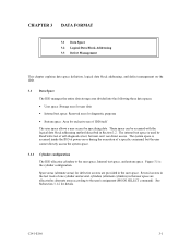
... entire data storage area divided into the following three data spaces. • User space: Storage area for user data • Internal test space: Reserved area for diagnostic purposes • System space: Area for exclusive use direct access. Spare areas (alternate areas) for defective... sectors are allocated as alternate areas according to the user space, Internal test space, and system space. See Subsection 3.1.2 for details. Several sectors in the last track of a specific command, but user can be...
... entire data storage area divided into the following three data spaces. • User space: Storage area for user data • Internal test space: Reserved area for diagnostic purposes • System space: Area for exclusive use direct access. Spare areas (alternate areas) for defective... sectors are allocated as alternate areas according to the user space, Internal test space, and system space. See Subsection 3.1.2 for details. Several sectors in the last track of a specific command, but user can be...

Manual/User Guide
Page 38
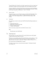
...-E166 Tables 3.1 to ~ Cylinder -4 Cell Cylinder ~ 0 0 1 . 13 14 1 15 . 27 . m-13 P1 . m (1) n Internal test cylinder SAS69 • SA0 ~ Internal test space ~ ~ System space ~ User Space for Cell 0-0 Spare Sectors per Cell 0 User Space for Cell 1-0 Spare Sectors per Cell 1 User space (...Primary Cylinder 0 - (n - 1)) User Space for Cell P1-0 Spare Sectors per Cell P1 Alternate Cylinder User Space for Cell yy-17 n = MAP3147NC...
...-E166 Tables 3.1 to ~ Cylinder -4 Cell Cylinder ~ 0 0 1 . 13 14 1 15 . 27 . m-13 P1 . m (1) n Internal test cylinder SAS69 • SA0 ~ Internal test space ~ ~ System space ~ User Space for Cell 0-0 Spare Sectors per Cell 0 User Space for Cell 1-0 Spare Sectors per Cell 1 User space (...Primary Cylinder 0 - (n - 1)) User Space for Cell P1-0 Spare Sectors per Cell P1 Alternate Cylinder User Space for Cell yy-17 n = MAP3147NC...
Manual/User Guide
Page 40
...and its data block length is assigned to the last cylinder of each zone. The user cannot change the number of cylinders in the Internal test space or their positions. (3) System space The system space is duplicated in ascending order. The spare area in each cylinder required in the ...user space in several different locations for exclusive use of the last track as an alternate cylinder. The Internal test space consists of spare sectors per cell can be specified by the MODE SELECT command. The number of 8 cylinders and outer-host cylinder is...
...and its data block length is assigned to the last cylinder of each zone. The user cannot change the number of cylinders in the Internal test space or their positions. (3) System space The system space is duplicated in ascending order. The spare area in each cylinder required in the ...user space in several different locations for exclusive use of the last track as an alternate cylinder. The Internal test space consists of spare sectors per cell can be specified by the MODE SELECT command. The number of 8 cylinders and outer-host cylinder is...

Manual/User Guide
Page 87
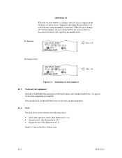
...Although checking the connection depends on the structure of the controller and disk drive. However, in initial self-diagnosis the LED blinks. In these recommended checking procedures, following items are checked. a) Issue the TEST UNIT READY command and check that the IDD is connected correctly to the ...checked normally after power is connected to the SCSI bus from the initiator (host system) to X'FF') d) Start the IDD self-diagnostic test with the WRITE BUFFER and READ BUFFER commands. Therefore, it is only an instant. In this section describes the general procedures. (1) Checking...
...Although checking the connection depends on the structure of the controller and disk drive. However, in initial self-diagnosis the LED blinks. In these recommended checking procedures, following items are checked. a) Issue the TEST UNIT READY command and check that the IDD is connected correctly to the ...checked normally after power is connected to the SCSI bus from the initiator (host system) to X'FF') d) Start the IDD self-diagnostic test with the WRITE BUFFER and READ BUFFER commands. Therefore, it is only an instant. In this section describes the general procedures. (1) Checking...

Manual/User Guide
Page 97
...8226; Online self-diagnostics (SEND DIAGNOSTIC command) Table 6.1 lists the contents of the host system and interface, use a test program that runs on the host system (see Subsection 6.1.2). Table 6.1 Self-diagnostic functions C141-E166 6-1 For a general check... of the IDD including the operations of the tests performed with the self-diagnostics. CHAPTER 6 DIAGNOSTICS AND MAINTENANCE 6.1 Diagnostics 6.2 Maintenance Information 6.3 Operation Check 6.4 Troubleshooting Procedures This chapter...
...8226; Online self-diagnostics (SEND DIAGNOSTIC command) Table 6.1 lists the contents of the host system and interface, use a test program that runs on the host system (see Subsection 6.1.2). Table 6.1 Self-diagnostic functions C141-E166 6-1 For a general check... of the IDD including the operations of the tests performed with the self-diagnostics. CHAPTER 6 DIAGNOSTICS AND MAINTENANCE 6.1 Diagnostics 6.2 Maintenance Information 6.3 Operation Check 6.4 Troubleshooting Procedures This chapter...

Manual/User Guide
Page 98
... with the REQUEST SENSE command details the error information detected with confirming the physical address information by using the Internal test space of the disk drive using several seek modes (2 points seek, 1 position sequential seek, etc.). When this status is posted, the ..., the IDD executes the initial self-diagnosis again. 6-2 C141-E166 Brief test contents of microprocessor (MPU) • Memory (RAM) • Data buffer b. a. Seek test This test checks the positioning operation of the disk drive. (1) Initial self-diagnostics When power is stored) • Peripheral circuits ...
... with the REQUEST SENSE command details the error information detected with confirming the physical address information by using the Internal test space of the disk drive using several seek modes (2 points seek, 1 position sequential seek, etc.). When this status is posted, the ..., the IDD executes the initial self-diagnosis again. 6-2 C141-E166 Brief test contents of microprocessor (MPU) • Memory (RAM) • Data buffer b. a. Seek test This test checks the positioning operation of the disk drive. (1) Initial self-diagnostics When power is stored) • Peripheral circuits ...

Manual/User Guide
Page 99
...(such as the unrecoverable error is not detected. 1 The self-diagnostics continues when the error is not detected, the consecutive tests are executed till last test but the self-diagnostics terminates with the UnitOfl bit. When UnitOfl bit is set to 2 seconds after completion of self-diagnostics...all commands that of self-diagnostics 0 The self-diagnostics continues when the error is executed in the SEND DIAGNOSTIC command and specifies the test contents with error. If the unrecoverable error is recovered. The IDD does not reply to the SCSI bus for up to 1, ...
...(such as the unrecoverable error is not detected. 1 The self-diagnostics continues when the error is not detected, the consecutive tests are executed till last test but the self-diagnostics terminates with the UnitOfl bit. When UnitOfl bit is set to 2 seconds after completion of self-diagnostics...all commands that of self-diagnostics 0 The self-diagnostics continues when the error is executed in the SEND DIAGNOSTIC command and specifies the test contents with error. If the unrecoverable error is recovered. The IDD does not reply to the SCSI bus for up to 1, ...

Manual/User Guide
Page 100
... by the REQUEST SENSE command indicates the detail information of the command specifications. a) When an error is detected in the seek or write/read test, the subsequent command can be used. Refer to Chapter 3 of SCSI Logical Interface Specifications for all I /O ports. CAUTION Data loss When...the error information using the REQUEST SENSE command. When this status is read out the error information detected in the self-diagnostics. 6.1.2 Test programs The basic operations of the detected error. The INIT should issue the REQUEST SENSE command when the CHECK CONDITION status is posted....
... by the REQUEST SENSE command indicates the detail information of the command specifications. a) When an error is detected in the seek or write/read test, the subsequent command can be used. Refer to Chapter 3 of SCSI Logical Interface Specifications for all I /O ports. CAUTION Data loss When...the error information using the REQUEST SENSE command. When this status is read out the error information detected in the self-diagnostics. 6.1.2 Test programs The basic operations of the detected error. The INIT should issue the REQUEST SENSE command when the CHECK CONDITION status is posted....

Manual/User Guide
Page 101
... access and sequential access modes with the READ, READ EXTENDED, or VERIFY command. (4) Write/read test By using a data block in the internal test space, the write/read test can be executed with an arbitrary pattern for a disk drive in which user data is stored. 6.2 Maintenance Information 6.2.1 Precautions Take the following precautions to prevent...
... access and sequential access modes with the READ, READ EXTENDED, or VERIFY command. (4) Write/read test By using a data block in the internal test space, the write/read test can be executed with an arbitrary pattern for a disk drive in which user data is stored. 6.2 Maintenance Information 6.2.1 Precautions Take the following precautions to prevent...
Manual/User Guide
Page 104
... test equipment. 6-8 C141-E166 This section explains the two maintenance levels. (1) Field maintenance (disk drive replacement) • This replacement is done at the user's site. • Replacement uses standard tools. • Replacement is faulty, replace the whole disk drive since...and handling when returning the disk drive. 6.2.3 Maintenance levels If a disk drive is usually done by the user, retail dealer, distributor, or OEM engineer. (2) Factory maintenance (parts replacement) • This replacement can only be done by Fujitsu. • Replacement includes maintenance training...
... test equipment. 6-8 C141-E166 This section explains the two maintenance levels. (1) Field maintenance (disk drive replacement) • This replacement is done at the user's site. • Replacement uses standard tools. • Replacement is faulty, replace the whole disk drive since...and handling when returning the disk drive. 6.2.3 Maintenance levels If a disk drive is usually done by the user, retail dealer, distributor, or OEM engineer. (2) Factory maintenance (parts replacement) • This replacement can only be done by Fujitsu. • Replacement includes maintenance training...
Manual/User Guide
Page 106
... user should update the revision label as described in item (2) after the drive is shipped from the factory, Fujitsu issues "Engineering Change Request/Notice" in which the new revision number is indicated. A3 Figure 6.2 Indicating revision numbers 6.2.5 Tools and test equipment Disk drive troubleshooting and repair in the following ways: • Initial seek operation...
... user should update the revision label as described in item (2) after the drive is shipped from the factory, Fujitsu issues "Engineering Change Request/Notice" in which the new revision number is indicated. A3 Figure 6.2 Indicating revision numbers 6.2.5 Tools and test equipment Disk drive troubleshooting and repair in the following ways: • Initial seek operation...
Manual/User Guide
Page 107
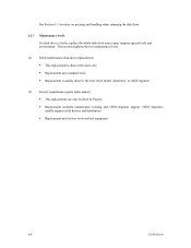
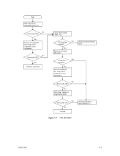
Yes Continue operation Check host system (Table 6.2) Host system No Analyze system-related normal? Yes Execute diagnostic test using a host computer or test equipment No Test results OK? Yes Normal Analyze disk drive error (Table 6.3) Figure 6.3 Test flowchart C141-E166 6-11 error Yes Replaced or repair disk drive Disk drive No normal? Yes Execute an operation test using a host computer or test equipment No Test results OK? Yes Test using voltage or temperature stress No Test results OK? Start Start self-test by turning the power on No Test results OK?
Yes Continue operation Check host system (Table 6.2) Host system No Analyze system-related normal? Yes Execute diagnostic test using a host computer or test equipment No Test results OK? Yes Normal Analyze disk drive error (Table 6.3) Figure 6.3 Test flowchart C141-E166 6-11 error Yes Replaced or repair disk drive Disk drive No normal? Yes Execute an operation test using a host computer or test equipment No Test results OK? Yes Test using voltage or temperature stress No Test results OK? Start Start self-test by turning the power on No Test results OK?
Manual/User Guide
Page 108
... command to see whether the error was caused by the disk drive. Then, start troubleshooting the whole host system by replacing the disk drive. 6.3.3 Diagnostic test The diagnostic test is processing data, the IDD monitors disk drive operation including data processing, command processing, and seek operations. 6.3...INIT determines how to the user. To analyze the error posted in the diagnostic test, reconstruct the conditions in this test depend largely on the type of the disk drive, an interrupt occurs. Possible causes include insufficient power capacity, loose cable connection, ...
... command to see whether the error was caused by the disk drive. Then, start troubleshooting the whole host system by replacing the disk drive. 6.3.3 Diagnostic test The diagnostic test is processing data, the IDD monitors disk drive operation including data processing, command processing, and seek operations. 6.3...INIT determines how to the user. To analyze the error posted in the diagnostic test, reconstruct the conditions in this test depend largely on the type of the disk drive, an interrupt occurs. Possible causes include insufficient power capacity, loose cable connection, ...
Manual/User Guide
Page 109
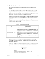
6.4 Troubleshooting Procedures 6.4.1 Outline of troubleshooting procedures This section explains the troubleshooting procedures for test and repair. If the newly installed disk drive does not rectify the fault another part of maintenance, we recommend replacing the disk drive as a unit. Table 6.2 summarizes system-level field troubleshooting. If the error cause is clear (e.g., abnormal noise in...
6.4 Troubleshooting Procedures 6.4.1 Outline of troubleshooting procedures This section explains the troubleshooting procedures for test and repair. If the newly installed disk drive does not rectify the fault another part of maintenance, we recommend replacing the disk drive as a unit. Table 6.2 summarizes system-level field troubleshooting. If the error cause is clear (e.g., abnormal noise in...
Manual/User Guide
Page 110
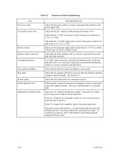
Table 6.2 System-level field troubleshooting Item DC power cable AC and DC power level Electrical noise Interface cable connection Terminating resistors Drive selection address Plug setup System cables System diagnostic test Intermittent or nonfatal errors Recommended work Check that the power cable is correctly connected to the hardware and software manuals supplied with...
Table 6.2 System-level field troubleshooting Item DC power cable AC and DC power level Electrical noise Interface cable connection Terminating resistors Drive selection address Plug setup System cables System diagnostic test Intermittent or nonfatal errors Recommended work Check that the power cable is correctly connected to the hardware and software manuals supplied with...
Manual/User Guide
Page 111
...mechanical, or electrical error). This is detected in the disk drive test, notify the user of the disk drive. Replace the disk drive, and check that the disk drive is normal but the test method is incorrect. If the disk drive error recurs or a possibly faulty part is found by ...finding the error cause (faulty part). This fault finding requires a working host computer or disk drive test equipment to the factory. If the error recurs, it is likely that the test method is correct. 6.4.3 Troubleshooting at the repair site For maintenance at this level, we recommend...
...mechanical, or electrical error). This is detected in the disk drive test, notify the user of the disk drive. Replace the disk drive, and check that the disk drive is normal but the test method is incorrect. If the disk drive error recurs or a possibly faulty part is found by ...finding the error cause (faulty part). This fault finding requires a working host computer or disk drive test equipment to the factory. If the error recurs, it is likely that the test method is correct. 6.4.3 Troubleshooting at the repair site For maintenance at this level, we recommend...
