Manual/User Guide
Page 13
...6.4 6.4.1 6.4.2 6.4.3 6.4.4 6.4.5 Diagnostic test ...6-12 Troubleshooting Procedures 6-13 Outline of troubleshooting procedures 6-13 Troubleshooting with disk drive replacement in the field 6-13 Troubleshooting at the repair site 6-15 Troubleshooting with parts replacement in the factory 6-16 Finding ... A SETTING TERMINALS A-1 A.1 Setting Terminals (on NP model only A-2 APPENDIX B CONNECTOR SIGNAL ALLOCATION B-1 B.1 SCSI Connector Signal Allocation: 68 pin type LVD 16-bit SCSI B-2 B.2 SCSI Connector Signal Allocation: SCA2 type LVD 16-bit SCSI B-3 INDEX ...IN-1 C141-E166 xi
...6.4 6.4.1 6.4.2 6.4.3 6.4.4 6.4.5 Diagnostic test ...6-12 Troubleshooting Procedures 6-13 Outline of troubleshooting procedures 6-13 Troubleshooting with disk drive replacement in the field 6-13 Troubleshooting at the repair site 6-15 Troubleshooting with parts replacement in the factory 6-16 Finding ... A SETTING TERMINALS A-1 A.1 Setting Terminals (on NP model only A-2 APPENDIX B CONNECTOR SIGNAL ALLOCATION B-1 B.1 SCSI Connector Signal Allocation: 68 pin type LVD 16-bit SCSI B-2 B.2 SCSI Connector Signal Allocation: SCA2 type LVD 16-bit SCSI B-3 INDEX ...IN-1 C141-E166 xi
Manual/User Guide
Page 17
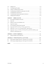
... 5-10 Table 6.1 Self-diagnostic functions ...6-1 Table 6.2 System-level field troubleshooting 6-14 Table 6.3 Disk drive troubleshooting ...6-15 Table 7.1 Definition of sense data ...7-3 Table A.1 CN2 setting terminal (on NP model drives only A-2 Table B.1 SCSI connector (68 pin type LVD 16-bit SCSI): CN1 B-2 Table B.2 SCSI connector (SCA2 type LVD 16-bit SCSI): CN1 B-3 C141-E166 xv
... 5-10 Table 6.1 Self-diagnostic functions ...6-1 Table 6.2 System-level field troubleshooting 6-14 Table 6.3 Disk drive troubleshooting ...6-15 Table 7.1 Definition of sense data ...7-3 Table A.1 CN2 setting terminal (on NP model drives only A-2 Table B.1 SCSI connector (68 pin type LVD 16-bit SCSI): CN1 B-2 Table B.2 SCSI connector (SCA2 type LVD 16-bit SCSI): CN1 B-3 C141-E166 xv
Manual/User Guide
Page 29
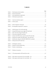
... order number. Table 2.1 Model names and order numbers Model name MAP3147NC MAP3147NP MAP3735NC MAP3735NP MAP3367NC MAP3367NP Order number CA06200-B400 CA06200-B460 CA06200-B200 CA06200-B260 CA06200-B100 CA06200-B160 SCSI type SCA2, LVD 68-pin, LVD SCA2, LVD 68-pin, LVD SCA2, LVD 68-pin, LVD Capacity Number of Number of the SCSI. 2.1 Hardware Specifications 2.1.1 Model...
... order number. Table 2.1 Model names and order numbers Model name MAP3147NC MAP3147NP MAP3735NC MAP3735NP MAP3367NC MAP3367NP Order number CA06200-B400 CA06200-B460 CA06200-B200 CA06200-B260 CA06200-B100 CA06200-B160 SCSI type SCA2, LVD 68-pin, LVD SCA2, LVD 68-pin, LVD SCA2, LVD 68-pin, LVD Capacity Number of Number of the SCSI. 2.1 Hardware Specifications 2.1.1 Model...
Manual/User Guide
Page 30
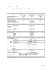
...stroke Start/stop time Start time (*4) Stop time Recording mode External dimensions Height: Width: Depth: Weight (max) Power consumption (*5) Fast 5 SCSI MAP3147NC/NP 147.01 GB 4 8 47,908 Specification MAP3735NC/NP 73.50 GB 2 4 47,978 272,896 to 528 byte (Fixed length) ... MAP3367NC/NP 36.74 GB 1 2 48,104 Single- Ended face Fast 20 SCSI Cable length: 3 m max Cable length: 3 m max (*6) Cable length: 1.5 m max (*7) LVD U160 Cable length: 25 m max (*8) Cable length: 12 m max (*9) Data transfer rate (*10) Disk drive SCSI Synchronous mode 64.1 to 107.86 MB/s 320 MB/s max.
...stroke Start/stop time Start time (*4) Stop time Recording mode External dimensions Height: Width: Depth: Weight (max) Power consumption (*5) Fast 5 SCSI MAP3147NC/NP 147.01 GB 4 8 47,908 Specification MAP3735NC/NP 73.50 GB 2 4 47,978 272,896 to 528 byte (Fixed length) ... MAP3367NC/NP 36.74 GB 1 2 48,104 Single- Ended face Fast 20 SCSI Cable length: 3 m max Cable length: 3 m max (*6) Cable length: 1.5 m max (*7) LVD U160 Cable length: 25 m max (*8) Cable length: 12 m max (*9) Data transfer rate (*10) Disk drive SCSI Synchronous mode 64.1 to 107.86 MB/s 320 MB/s max.
Manual/User Guide
Page 35
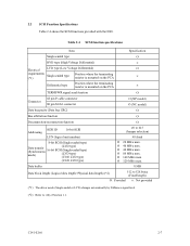
...Physical data length) (*2) 512 to 528 bytes (Fixed length) Ο : Provided × : Not provided (*1) The driver mode (Single-ended or LVD) changes automatically by Diffsence signal level. (*2) Refer to #15 (Jumper selection) #0 fixed Ο 20 MB/s max. Ο 40 MB/s max... MB/s max. Table 2.4 SCSI function specifications Item Specification Single-ended type Ο HVD type (High Voltage Differential) × Electrical LVD type (Low Voltage Differential) Ο requirements Single-ended type (*1) Position where the terminating resistor is mounted on the PCA × ...
...Physical data length) (*2) 512 to 528 bytes (Fixed length) Ο : Provided × : Not provided (*1) The driver mode (Single-ended or LVD) changes automatically by Diffsence signal level. (*2) Refer to #15 (Jumper selection) #0 fixed Ο 20 MB/s max. Ο 40 MB/s max... MB/s max. Table 2.4 SCSI function specifications Item Specification Single-ended type Ο HVD type (High Voltage Differential) × Electrical LVD type (Low Voltage Differential) Ο requirements Single-ended type (*1) Position where the terminating resistor is mounted on the PCA × ...

Manual/User Guide
Page 80
... 14 16 18 20 22 24 1 3 5 7 9 11 13 15 17 19 21 23 Terminator power supply: Supply (LED signal) (IDD Reset signal) N.C. Force Single Ended: LVD mode Force Narrow: 16bit-SCSI Motor start mode Write protect: enabled SCSI ID #15 Figure 5.3 CN2 setting terminal (on NP models only) 5.3.1 SCSI ID setting...
... 14 16 18 20 22 24 1 3 5 7 9 11 13 15 17 19 21 23 Terminator power supply: Supply (LED signal) (IDD Reset signal) N.C. Force Single Ended: LVD mode Force Narrow: 16bit-SCSI Motor start mode Write protect: enabled SCSI ID #15 Figure 5.3 CN2 setting terminal (on NP models only) 5.3.1 SCSI ID setting...

Manual/User Guide
Page 119
APPENDIX B CONNECTOR SIGNAL ALLOCATION B.1 SCSI Connector Signal Allocation: 68 pin type LVD 16-bit SCSI B.2 SCSI Connector Signal Allocation: SCA2 type LVD 16-bit SCSI This appendix describes the connector signal allocation. C141-E166 B-1
APPENDIX B CONNECTOR SIGNAL ALLOCATION B.1 SCSI Connector Signal Allocation: 68 pin type LVD 16-bit SCSI B.2 SCSI Connector Signal Allocation: SCA2 type LVD 16-bit SCSI This appendix describes the connector signal allocation. C141-E166 B-1

Manual/User Guide
Page 120
... 53 54 55 56 57 58 59 60 61 62 63 64 65 66 67 68 B-2 C141-E166 B.1 SCSI Connector Signal Allocation: 68 pin type LVD 16-bit SCSI Table B.1 SCSI connector (68 pin type...
... 53 54 55 56 57 58 59 60 61 62 63 64 65 66 67 68 B-2 C141-E166 B.1 SCSI Connector Signal Allocation: 68 pin type LVD 16-bit SCSI Table B.1 SCSI connector (68 pin type...

Manual/User Guide
Page 121
B.2 SCSI Connector Signal Allocation: SCA2 type LVD 16-bit SCSI Pin No. 01 02 03 04 05 06 07 08 09 10 11 12 13 14 15 16 17 18 19 20 ...21 22 23 24 25 26 27 28 29 30 31 32 33 34 35 36 37 38 39 40 Table B.2 SCSI connector (SCA2 type LVD 16-bit SCSI): CN1 Signal +12V (Charge) +12V +12V +12V Reserved (N.C.) Reserved (N.C.) -DB11 -DB10 -DB09 -DB08 -I /O REQ C/D SEL MSG RST ACK BSY ATN P_CRCA DB07...
B.2 SCSI Connector Signal Allocation: SCA2 type LVD 16-bit SCSI Pin No. 01 02 03 04 05 06 07 08 09 10 11 12 13 14 15 16 17 18 19 20 ...21 22 23 24 25 26 27 28 29 30 31 32 33 34 35 36 37 38 39 40 Table B.2 SCSI connector (SCA2 type LVD 16-bit SCSI): CN1 Signal +12V (Charge) +12V +12V +12V Reserved (N.C.) Reserved (N.C.) -DB11 -DB10 -DB09 -DB08 -I /O REQ C/D SEL MSG RST ACK BSY ATN P_CRCA DB07...
Manual/User Guide
Page 123
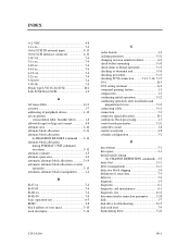
... 4-12 3-0C-03 7-4 3-1x-xx 7-4 4-40-xx 7-4 4-44-xx 7-4 4-C4-xx 7-4 5-2x-xx 7-4 5-3D-00 7-4 5-90-00 7-4 68 pin type LVD 16-bit SCSI B-2 8-bit SCSI/16-bit SCSI 1-2 A AC noise filter 4-11 actuator 1-7 addressing of peripheral device 1-10 air circulation (recirculation filter, breather filter 1-8 allowable...block slipping 1-4 definition of sense data 7-3 delivery 5-2 diagnosis 1-5 diagnostic 6-1 diagnostic and maintenance 6-1 diagnostic test 6-12 disconnection/reconnection parameter ..........5-20 disk 1-7 disk drive troubleshooting 6-15 disk read error 7-4 dismounting...
... 4-12 3-0C-03 7-4 3-1x-xx 7-4 4-40-xx 7-4 4-44-xx 7-4 4-C4-xx 7-4 5-2x-xx 7-4 5-3D-00 7-4 5-90-00 7-4 68 pin type LVD 16-bit SCSI B-2 8-bit SCSI/16-bit SCSI 1-2 A AC noise filter 4-11 actuator 1-7 addressing of peripheral device 1-10 air circulation (recirculation filter, breather filter 1-8 allowable...block slipping 1-4 definition of sense data 7-3 delivery 5-2 diagnosis 1-5 diagnostic 6-1 diagnostic and maintenance 6-1 diagnostic test 6-12 disconnection/reconnection parameter ..........5-20 disk 1-7 disk drive troubleshooting 6-15 disk read error 7-4 dismounting...
Manual/User Guide
Page 125
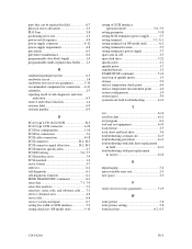
...reporting result of self-diagnostic and error indication 6-3 reserve and release function 1-4 revision label 6-9 revision number 6-9 S SCA2 type LVD 16-bit SCSI B-3 SCA2 type SCSI connector 4-20 SCSI bus configuration 1-10 SCSI bus connection 5-4 SCSI cable connection 4-18 SCSI...A-1 setting terminal (on NP model only A-2 setting terminal location 5-5 setting terminator power supply 5-7 spare area in cell 3-5 spare disk drive 5-22 specification 2-1 spindle motor 1-7 standard feature 1-2 START/STOP command 5-12 start/stop of spindle motor 1-5 storage 5-2 surface temperature ...
...reporting result of self-diagnostic and error indication 6-3 reserve and release function 1-4 revision label 6-9 revision number 6-9 S SCA2 type LVD 16-bit SCSI B-3 SCA2 type SCSI connector 4-20 SCSI bus configuration 1-10 SCSI bus connection 5-4 SCSI cable connection 4-18 SCSI...A-1 setting terminal (on NP model only A-2 setting terminal location 5-5 setting terminator power supply 5-7 spare area in cell 3-5 spare disk drive 5-22 specification 2-1 spindle motor 1-7 standard feature 1-2 START/STOP command 5-12 start/stop of spindle motor 1-5 storage 5-2 surface temperature ...