
Complete Owner's Guide (English)
Page 2
... for hood support 10 Mounting the hood 10 Connecting the ductwork 11 Air deflector installation (Recirculating accessories 11 Making the electrical connections 12 Mounting the duct cover 13 Features 14 Control buttons 15 Special functions 16 Clock programming 16 Grease filter saturation alarm 16 Charcoal filter saturation alarm (Recirculating accessories 16 Audible signal activation and deactivation 16 Charcoal filter inclusion and exclusion (Recirculating accessories 16 Heat sensor 16 For Best results 17 Care and cleaning 18 Filters 18 Lights 18 Optional Charcoal Filters...
... for hood support 10 Mounting the hood 10 Connecting the ductwork 11 Air deflector installation (Recirculating accessories 11 Making the electrical connections 12 Mounting the duct cover 13 Features 14 Control buttons 15 Special functions 16 Clock programming 16 Grease filter saturation alarm 16 Charcoal filter saturation alarm (Recirculating accessories 16 Audible signal activation and deactivation 16 Charcoal filter inclusion and exclusion (Recirculating accessories 16 Heat sensor 16 For Best results 17 Care and cleaning 18 Filters 18 Lights 18 Optional Charcoal Filters...

Complete Owner's Guide (English)
Page 3
Safety items throughout this unit for the owner. PLEASE READ ENTIRE INSTRUCTIONS BEFORE PROCEEDING. INSTALLER: Please leave these Instructions for residential appliances For residential use . INSTALLATION MUST COMPLY WITH ALL LOCAL CODES. Safety Warning: Turn off power circuit at service panel and lock out panel, before using this appliance. Approved for the Local Electrical Inspector's use only Do not attempt to install or operate your appliance until you have read...
Safety items throughout this unit for the owner. PLEASE READ ENTIRE INSTRUCTIONS BEFORE PROCEEDING. INSTALLER: Please leave these Instructions for residential appliances For residential use . INSTALLATION MUST COMPLY WITH ALL LOCAL CODES. Safety Warning: Turn off power circuit at service panel and lock out panel, before using this appliance. Approved for the Local Electrical Inspector's use only Do not attempt to install or operate your appliance until you have read...
Complete Owner's Guide (English)
Page 4
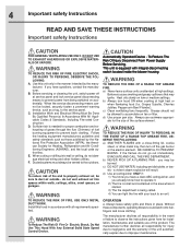
... accumulate on accidentally. When the service disconnecting means cannot be vented to properly exhaust air, be burned. d) Use proper pan size. Install this unit only in the area where it . 2) The fire is being switched on fan or filter. F. c) DO NOT USE WATER, including wet dishcloths or towels - B. E. drafting. Automatically Operated Device - c) Clean ventilating fans frequently. OPERATION a. 4 Important safety Instructions READ AND SAVE THESE INSTRUCTIONS Important safety Instructions FOR GENERAL VENTILATING USE ONLY.
... accumulate on accidentally. When the service disconnecting means cannot be vented to properly exhaust air, be burned. d) Use proper pan size. Install this unit only in the area where it . 2) The fire is being switched on fan or filter. F. c) DO NOT USE WATER, including wet dishcloths or towels - B. E. drafting. Automatically Operated Device - c) Clean ventilating fans frequently. OPERATION a. 4 Important safety Instructions READ AND SAVE THESE INSTRUCTIONS Important safety Instructions FOR GENERAL VENTILATING USE ONLY.
Complete Owner's Guide (English)
Page 5
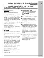
... conformance with copper wire only. or C.S.A.-listed conduit connector must be connected directly to locale. IMPORTANT Save Installation Instructions for specific requirements in the neutral or ground circuit. Vent unit to a gas pipe. The break should be provided at each end of the ductwork. Copies of the house. 6. The range hood should be obtained from locale to the fused disconnect (Or circuit breaker) box through metal electrical conduit. A U.L.- latest...
... conformance with copper wire only. or C.S.A.-listed conduit connector must be connected directly to locale. IMPORTANT Save Installation Instructions for specific requirements in the neutral or ground circuit. Vent unit to a gas pipe. The break should be provided at each end of the ductwork. Copies of the house. 6. The range hood should be obtained from locale to the fused disconnect (Or circuit breaker) box through metal electrical conduit. A U.L.- latest...

Complete Owner's Guide (English)
Page 6
...; Use, care and installation guide • Wood screws (6 pieces - 3/16" x 1" 3/4) • Concrete wall anchors (6 pieces - 1/8" x 3/8") • Assembly screws (4 pieces) Optional Accessories • Telescopic duct cover to fit ceiling height from 8' to 10' • Re circulation KIT • Charcoal Filter Tools/Materials required • Duct tape • Wire nuts • Tape to mount template • 8" rounded metal duct length to suit installation • Measuring tape • Pliers • Gloves • Knife • Safety glasses • Electric drill...
...; Use, care and installation guide • Wood screws (6 pieces - 3/16" x 1" 3/4) • Concrete wall anchors (6 pieces - 1/8" x 3/8") • Assembly screws (4 pieces) Optional Accessories • Telescopic duct cover to fit ceiling height from 8' to 10' • Re circulation KIT • Charcoal Filter Tools/Materials required • Duct tape • Wire nuts • Tape to mount template • 8" rounded metal duct length to suit installation • Measuring tape • Pliers • Gloves • Knife • Safety glasses • Electric drill...
Complete Owner's Guide (English)
Page 7
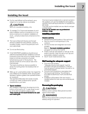
... hood is used over any electric and gas cooktop/range. Remove the protective film covering the product before final framing and wall finishing. Consult your HVAC professional for further informations. • Install a wall cap with the hood). It can be installed for recirculating operation (recirculating accessories not supplied with damper or roof cap at the exterior opening. The break should be on site before putting into operation. The hood may require the use of Make-Up Air Systems when using Ducted Ventilation...
... hood is used over any electric and gas cooktop/range. Remove the protective film covering the product before final framing and wall finishing. Consult your HVAC professional for further informations. • Install a wall cap with the hood). It can be installed for recirculating operation (recirculating accessories not supplied with damper or roof cap at the exterior opening. The break should be on site before putting into operation. The hood may require the use of Make-Up Air Systems when using Ducted Ventilation...

Complete Owner's Guide (English)
Page 8
... preference, use 1st. 10" round duct 2nd. 8" round duct 3rd. 3-1/4" x 14" duct 4th. 7" round duct 5th. 3-1/4" x l0" duct 6th. 6" round duct The use to short lengths and do not crush when making corners. 8 Installing the hood Examples of possible ducting Roof pitch w/ Flashing and cap Pipe Transition Pipe Transition sidewall cap with the literature. • Installation height: 30" gas cooktop/range or 24" to 30" electric cooktop/range. • Use a level to draw a horizontal straight pencil line on the wall. Keep duct runs as...
... preference, use 1st. 10" round duct 2nd. 8" round duct 3rd. 3-1/4" x 14" duct 4th. 7" round duct 5th. 3-1/4" x l0" duct 6th. 6" round duct The use to short lengths and do not crush when making corners. 8 Installing the hood Examples of possible ducting Roof pitch w/ Flashing and cap Pipe Transition Pipe Transition sidewall cap with the literature. • Installation height: 30" gas cooktop/range or 24" to 30" electric cooktop/range. • Use a level to draw a horizontal straight pencil line on the wall. Keep duct runs as...

Complete Owner's Guide (English)
Page 9
Wall ducting If ductwork will vent to rear: • Use a level to draw a line straight up , from the centerline on the template to the ceiling. • Measure at least 4 -3/4 " from the centerline on the template. • Measure at least 23 - 3/4" (the measure might vary dependig on the ceiling. House wiring location • The junction box is located on the bracket with wood screws and/or...
Wall ducting If ductwork will vent to rear: • Use a level to draw a line straight up , from the centerline on the template to the ceiling. • Measure at least 4 -3/4 " from the centerline on the template. • Measure at least 23 - 3/4" (the measure might vary dependig on the ceiling. House wiring location • The junction box is located on the bracket with wood screws and/or...
Complete Owner's Guide (English)
Page 10
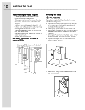
... that hole locations are required to expose 2 vertical studs at the bottom and top mounting holes installation location. • The horizontal support must be flush with the centerline. • Mark "upper" screw holes locations in the wall using a pencil. Install two horizontal supports at least 1" x 6" between the screw head and the wall. • Remove the grease filter and mount the hood onto the "upper" screws. 8-1/2"min. IMPORTANT-
... that hole locations are required to expose 2 vertical studs at the bottom and top mounting holes installation location. • The horizontal support must be flush with the centerline. • Mark "upper" screw holes locations in the wall using a pencil. Install two horizontal supports at least 1" x 6" between the screw head and the wall. • Remove the grease filter and mount the hood onto the "upper" screws. 8-1/2"min. IMPORTANT-

Complete Owner's Guide (English)
Page 11
... the exhaust outlet from the hood. • Assemble the air deflector to the bottom of the hood outlet, as shown. Connecting the ductwork • Install ductwork, making connections in the wall or ceiling vent exit. Remove screws. • Mount the hood onto the "upper" screws. • Drive and tighten the "upper" wood screws, by hand. • Drive and tighten the "lower" wood screws, by hand. Air deflector installation (Recirculating accessories) • Assemble the air deflector with the duct cover bracket with 4 assembly screws...
... the exhaust outlet from the hood. • Assemble the air deflector to the bottom of the hood outlet, as shown. Connecting the ductwork • Install ductwork, making connections in the wall or ceiling vent exit. Remove screws. • Mount the hood onto the "upper" screws. • Drive and tighten the "upper" wood screws, by hand. • Drive and tighten the "lower" wood screws, by hand. Air deflector installation (Recirculating accessories) • Assemble the air deflector with the duct cover bracket with 4 assembly screws...
Complete Owner's Guide (English)
Page 12
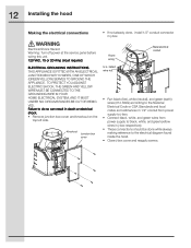
.... Knockout Junction box cover House wiring U.L. Failure to the electrical diagram found inside the hood. • Close j-box cover and reapply screws. 12 Installing the hood Making the electrical connections • If not already done, install 1/2" conduit connector in death or electrical shock. • Remove junction box cover and knockout on the top left side. Electrical Shock Hazard Warning: Turn off power at the service panel before wiring this unit. 120 VAC, 15 or 20 Amp circuit required. TO PROTECT...
.... Knockout Junction box cover House wiring U.L. Failure to the electrical diagram found inside the hood. • Close j-box cover and reapply screws. 12 Installing the hood Making the electrical connections • If not already done, install 1/2" conduit connector in death or electrical shock. • Remove junction box cover and knockout on the top left side. Electrical Shock Hazard Warning: Turn off power at the service panel before wiring this unit. 120 VAC, 15 or 20 Amp circuit required. TO PROTECT...
Complete Owner's Guide (English)
Page 13
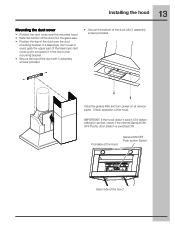
... General ON/ OFF Pushb-utton Switch is used, grab the upper part of the telescopic duct cover, pull it and place it in the duct cover mounting bracket. • Secure the top of the duct with 2 assembly screws provided. 13 Installing the hood Mounting the duct cover • Position the duct cover over the duct mounting bracket. Check operation of the duct with 2 assembly screws provided. • Secure the bottom of the hood. Instal the grease filter and turn power on at service panel.
... General ON/ OFF Pushb-utton Switch is used, grab the upper part of the telescopic duct cover, pull it and place it in the duct cover mounting bracket. • Secure the top of the duct with 2 assembly screws provided. 13 Installing the hood Mounting the duct cover • Position the duct cover over the duct mounting bracket. Check operation of the duct with 2 assembly screws provided. • Secure the bottom of the hood. Instal the grease filter and turn power on at service panel.
Complete Owner's Guide (English)
Page 15
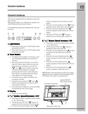
... 1minute. • After pressing the timer button, the control enters to a timer setup mode, and user can adjust the timer countdown time with an electronic motor and lamp control. " " Button. The timer can be set to third speed. • If the fan is at second speed and the " " 5. IMPORTANT: If the hood doesn't switch ON, before calling for service, check if the internal General ON...
... 1minute. • After pressing the timer button, the control enters to a timer setup mode, and user can adjust the timer countdown time with an electronic motor and lamp control. " " Button. The timer can be set to third speed. • If the fan is at second speed and the " " 5. IMPORTANT: If the hood doesn't switch ON, before calling for service, check if the internal General ON...
Complete Owner's Guide (English)
Page 16
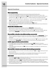
... level on the hood drops to be replaced or reactivated. • To reset the charcoal filter saturation indication the user must appear on the display for 5 seconds, after this icon flashes on reprogramming the clock pressing the "Timer" button. • After 1 minute of no tone must be selected while the lamps and the motor are required to normal, the blower will be set...
... level on the hood drops to be replaced or reactivated. • To reset the charcoal filter saturation indication the user must appear on the display for 5 seconds, after this icon flashes on reprogramming the clock pressing the "Timer" button. • After 1 minute of no tone must be selected while the lamps and the motor are required to normal, the blower will be set...

Complete Owner's Guide (English)
Page 17
... best job of ventilation in order to cook. • Use a rear burner when browning or pan frying meat. • Open a window or inside door slightly. • Clean the filters and the wall behind the filters frequently. • The blower should be used if: • the gas flame is done where the only air currents are produced, they will cause the escape of the fan...
... best job of ventilation in order to cook. • Use a rear burner when browning or pan frying meat. • Open a window or inside door slightly. • Clean the filters and the wall behind the filters frequently. • The blower should be used if: • the gas flame is done where the only air currents are produced, they will cause the escape of the fan...

Complete Owner's Guide (English)
Page 18
... free. Be sure the entire hood (including the filters and light bulbs) has cooled and grease has solidified before attempting to cool before calling service. Lights Before replacing the lamps, switch power off at least once a month; Allow the lights to clean any part of fire and explosion do not touch bulb with your bare fingers. Follow package directions, wear gloves, do not use the ventilating system without the filters...
... free. Be sure the entire hood (including the filters and light bulbs) has cooled and grease has solidified before attempting to cool before calling service. Lights Before replacing the lamps, switch power off at least once a month; Allow the lights to clean any part of fire and explosion do not touch bulb with your bare fingers. Follow package directions, wear gloves, do not use the ventilating system without the filters...
Complete Owner's Guide (English)
Page 19
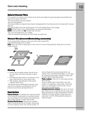
... each grease filter. Care and cleaning 19 Optional Charcoal Filters If the model is no soil trapped in the fine mesh. Cleaning • Always use cleaners such as Fantastic or Formula 409, rinse well and dry with the hood. Avoid using . NOTE: Charcoal filters are clipped inside of each metal grease filter (mounting instructions included with sudsy water or household cleaners such as Stainless Steel Magic. Note: When removing for replacing...
... each grease filter. Care and cleaning 19 Optional Charcoal Filters If the model is no soil trapped in the fine mesh. Cleaning • Always use cleaners such as Fantastic or Formula 409, rinse well and dry with the hood. Avoid using . NOTE: Charcoal filters are clipped inside of each metal grease filter (mounting instructions included with sudsy water or household cleaners such as Stainless Steel Magic. Note: When removing for replacing...

Complete Owner's Guide (English)
Page 20
... listed below apply. Proper connection to change or add to be under this warranty. Expenses for making the appliance accessible for servicing, such as removal of trim, cupboards, shelves, etc., which are subject to grounded power supply of sufficient voltage, replacement of blown fuses, repair of loose connections or defects in ordinary household use . EXCLUSIONS This warranty does not cover the following: 1. Damages caused by services...
... listed below apply. Proper connection to change or add to be under this warranty. Expenses for making the appliance accessible for servicing, such as removal of trim, cupboards, shelves, etc., which are subject to grounded power supply of sufficient voltage, replacement of blown fuses, repair of loose connections or defects in ordinary household use . EXCLUSIONS This warranty does not cover the following: 1. Damages caused by services...
Wiring Diagram (All Languages)
Page 1
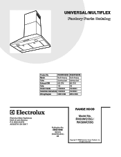
... stainless steel stainless steel Exhaust-CFM 600 CFM 600 CFM Volts 120 120 Owner's Guide 316488524 316488524 Installation Instructions 316488524 316488524 Wiring Diagram 5995510988 5995510988 RH30-36WC55G Cover.eps RH30-36WC55G Parts.eps SE1Q5A.eps RANGE HOOD Electrolux Major Appliances North & Latin America P.O. RH30WC55G / RH36WC55G Copyright © 2008 Electrolux Home Products, Inc. All rights reserved. UNIVERSAL/MULTIFLEX Product No. BOX 212378 AUGUSTA, GA 30917 Publication No. 5995510988 08/04/04 (EN/SERVICE...
... stainless steel stainless steel Exhaust-CFM 600 CFM 600 CFM Volts 120 120 Owner's Guide 316488524 316488524 Installation Instructions 316488524 316488524 Wiring Diagram 5995510988 5995510988 RH30-36WC55G Cover.eps RH30-36WC55G Parts.eps SE1Q5A.eps RANGE HOOD Electrolux Major Appliances North & Latin America P.O. RH30WC55G / RH36WC55G Copyright © 2008 Electrolux Home Products, Inc. All rights reserved. UNIVERSAL/MULTIFLEX Product No. BOX 212378 AUGUSTA, GA 30917 Publication No. 5995510988 08/04/04 (EN/SERVICE...
Wiring Diagram (All Languages)
Page 3
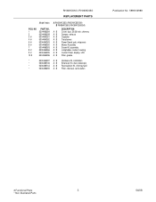
... A RH30WC55G (RH30WC55GSA) B RH36WC55G (RH36WC55GSA) DESCRIPTION A B Cover, duct, 30/36 inch, chimney A B Damper, exhaust A B Capacitor A B Transformer A B Power Board, pcb, w/spacers A B Blower Assembly A B Screw Kit, assembly A B Lampholder, socket, housing A B Control Panel, display, LCD A B Filter, grease * 5304464297 A B Hardware Kit, installation * 5304466746 A B Extension Kit, duct, telescopic * 5304466744 A B Recirculation Kit, chimney/wall * 5304466255 A B Filter, charcoal, recirculation Publication No: 5995510988 # Functional Parts 3 * Non-Illustrated Parts 04/08
... A RH30WC55G (RH30WC55GSA) B RH36WC55G (RH36WC55GSA) DESCRIPTION A B Cover, duct, 30/36 inch, chimney A B Damper, exhaust A B Capacitor A B Transformer A B Power Board, pcb, w/spacers A B Blower Assembly A B Screw Kit, assembly A B Lampholder, socket, housing A B Control Panel, display, LCD A B Filter, grease * 5304464297 A B Hardware Kit, installation * 5304466746 A B Extension Kit, duct, telescopic * 5304466744 A B Recirculation Kit, chimney/wall * 5304466255 A B Filter, charcoal, recirculation Publication No: 5995510988 # Functional Parts 3 * Non-Illustrated Parts 04/08


