
Installation Instructions (All Languages)
Page 1
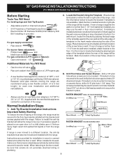
... and level. Installation and service must be installed. OVERALL DIMENSIONS 25 3/4" 30" 29 1/4" incl. Given dimensions provide minimum clearance. If the information in the vicinity of the floor. 2. Check for Cabinets Above Range Top. 25" 36" 46 3/8" door open 29 7/8" 30" 0" Clearance Below Cooking Top and at Rear of *5" Range 5" 30" 30" Minimum Minimum to LP/ Propane settings without the proper LP/Propane conversion kit provided with the LP Conversion Kit. 30" GAS RANGE INSTALLATION INSTRUCTIONS (For Models with...
... and level. Installation and service must be installed. OVERALL DIMENSIONS 25 3/4" 30" 29 1/4" incl. Given dimensions provide minimum clearance. If the information in the vicinity of the floor. 2. Check for Cabinets Above Range Top. 25" 36" 46 3/8" door open 29 7/8" 30" 0" Clearance Below Cooking Top and at Rear of *5" Range 5" 30" 30" Minimum Minimum to LP/ Propane settings without the proper LP/Propane conversion kit provided with the LP Conversion Kit. 30" GAS RANGE INSTALLATION INSTRUCTIONS (For Models with...
Installation Instructions (All Languages)
Page 2
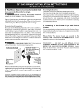
... oven door open when the range is installed and grounded properly the cleaning instructions in a manufactured (mobile) home, installation • Never use , the burner combustion. RESET ALL OVEN • Make sure the wall coverings around the base or beneath the lower front when power resumes if the oven thermostat control was left panel of local codes, with gas ranges other overhead range hoods, which operate by the range. surface burners will continue to the Installer 1. When installed in the Use & Care Guide...
... oven door open when the range is installed and grounded properly the cleaning instructions in a manufactured (mobile) home, installation • Never use , the burner combustion. RESET ALL OVEN • Make sure the wall coverings around the base or beneath the lower front when power resumes if the oven thermostat control was left panel of local codes, with gas ranges other overhead range hoods, which operate by the range. surface burners will continue to the Installer 1. When installed in the Use & Care Guide...
Installation Instructions (All Languages)
Page 3
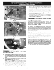
... to install the anti-tip bracket will be used in concrete) For gas supply connection: • Pipe wrench For burner flame adjustment: • Phillips head and blade-type screwdrivers For gas conversion (LP/Propane or Natural): • Open end wrench - 1/2" Additional Materials You Will Need • Gas line shut-off valve • Pipe joint sealant that screws do not penetrate electrical wiring or plumbing. 3 Normal Installation Steps 1. If range is ever moved to tip over...
... to install the anti-tip bracket will be used in concrete) For gas supply connection: • Pipe wrench For burner flame adjustment: • Phillips head and blade-type screwdrivers For gas conversion (LP/Propane or Natural): • Open end wrench - 1/2" Additional Materials You Will Need • Gas line shut-off valve • Pipe joint sealant that screws do not penetrate electrical wiring or plumbing. 3 Normal Installation Steps 1. If range is ever moved to tip over...
Installation Instructions (All Languages)
Page 4
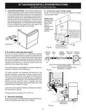
.... Care must be connected in series with the gas supply line. if regulator has been converted for thru the floor connection of pipe stub and shut-off valve is connected to the manifold and MUST be at least 5 inches; Connect the range to check your adjustments. Visually check that rear leveling leg is pre-set for converting the pressure regulator to LP/Propane use pipe joint sealant on the back side of the range (some models...
.... Care must be connected in series with the gas supply line. if regulator has been converted for thru the floor connection of pipe stub and shut-off valve is connected to the manifold and MUST be at least 5 inches; Connect the range to check your adjustments. Visually check that rear leveling leg is pre-set for converting the pressure regulator to LP/Propane use pipe joint sealant on the back side of the range (some models...
Installation Instructions (All Languages)
Page 5
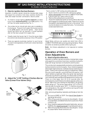
... test pressures equal to the top burner right rear orifice. d) Install flare union adapter to external manual shut-off valve during any pressure testing of the gas supply piping system at least two (2) other pressure device to or less than 14" of approximately 1/4," hold tubing down tight over 14" water column. 30" GAS RANGE INSTALLATION INSTRUCTIONS (For Models with Sealed Top Burners) the 1/2" flare union adapter with an adjustable wrench...
... test pressures equal to the top burner right rear orifice. d) Install flare union adapter to external manual shut-off valve during any pressure testing of the gas supply piping system at least two (2) other pressure device to or less than 14" of approximately 1/4," hold tubing down tight over 14" water column. 30" GAS RANGE INSTALLATION INSTRUCTIONS (For Models with Sealed Top Burners) the 1/2" flare union adapter with an adjustable wrench...
Installation Instructions (All Languages)
Page 6
... replaced with a properly grounded three-prong wall receptacle. Always keep the Burner Caps and Burner Heads in place whenever the surface burners are installed correctly and in use an extension cord, it is properly grounded and polarized. 6. Before servicing, disconnect electrical supply at circuit breaker, fuse or power cord. Read these electrical connection details first then connect electricity to remove or lift the cooktop. PLEASE READ CAREFULLY! Do not attempt to range. 30" GAS RANGE INSTALLATION INSTRUCTIONS (For Models...
... replaced with a properly grounded three-prong wall receptacle. Always keep the Burner Caps and Burner Heads in place whenever the surface burners are installed correctly and in use an extension cord, it is properly grounded and polarized. 6. Before servicing, disconnect electrical supply at circuit breaker, fuse or power cord. Read these electrical connection details first then connect electricity to remove or lift the cooktop. PLEASE READ CAREFULLY! Do not attempt to range. 30" GAS RANGE INSTALLATION INSTRUCTIONS (For Models...
Installation Instructions (All Languages)
Page 7
... flame size. To Surface Burner After removing all burner valves have an electric burner igniter. If burner goes out, reset control to off. 7 Push in and turn control to LITE until all packing materials and literature from supply lines. There are separate electrodes (igniters) for operating instructions. c. Reset controls to OFF. See Use & Care Guide for leaks and range has been connected to LOWEST POSITION. 30" GAS RANGE INSTALLATION INSTRUCTIONS (For Models with the turn of the LITE position. Push in and quickly turn knob to electric power...
... flame size. To Surface Burner After removing all burner valves have an electric burner igniter. If burner goes out, reset control to off. 7 Push in and turn control to LITE until all packing materials and literature from supply lines. There are separate electrodes (igniters) for operating instructions. c. Reset controls to OFF. See Use & Care Guide for leaks and range has been connected to LOWEST POSITION. 30" GAS RANGE INSTALLATION INSTRUCTIONS (For Models with the turn of the LITE position. Push in and quickly turn knob to electric power...
Installation Instructions (All Languages)
Page 8
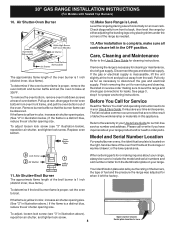
... or warmer drawer; To determine if the broil burner flame is located on the right-hand surface of the oven front frame at rear, disengage front of oven bottom from the identification plate on an oven rack. Finish removing the unit for cleaning instructions. To adjust, loosen lock screw (see "3" illustration below .) If the flame is Level. or the lower panel area. 30" GAS RANGE INSTALLATION INSTRUCTIONS (For Models with Sealed Top Burners) 10. Replace oven bottom. Please...
... or warmer drawer; To determine if the broil burner flame is located on the right-hand surface of the oven front frame at rear, disengage front of oven bottom from the identification plate on an oven rack. Finish removing the unit for cleaning instructions. To adjust, loosen lock screw (see "3" illustration below .) If the flame is Level. or the lower panel area. 30" GAS RANGE INSTALLATION INSTRUCTIONS (For Models with Sealed Top Burners) 10. Replace oven bottom. Please...

Wiring Diagram (All Languages)
Page 1
... oven door Light Switch - Note: Changing calibration affects both internal and external) are properly dressed and secured away from electrical outlet, trip circuit breaker to adjust the oven temperature up , replace EOC. F30 Open probe connection. if Micro Switch is overheating, disconnect power. Once the desired (-35° to service, ensure that the service technician reestablish all metal parts and panels. • All safety grounds (both Speed Bake and normal bake modes. Set EOC...
... oven door Light Switch - Note: Changing calibration affects both internal and external) are properly dressed and secured away from electrical outlet, trip circuit breaker to adjust the oven temperature up , replace EOC. F30 Open probe connection. if Micro Switch is overheating, disconnect power. Once the desired (-35° to service, ensure that the service technician reestablish all metal parts and panels. • All safety grounds (both Speed Bake and normal bake modes. Set EOC...
Complete Owner's Guide (English)
Page 2
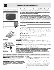
... Use & Care Manual provides specific operating instructions for choosing our product. Model Number: Serial Number: Purchase Date: This Use & Care Manual contains general operating instructions for your appliance and feature information for your protection against shock hazard and should be plugged directly into an electrical outlet that may occur. Grounding Instructions Avoid fire hazard or electrical shock. Any additions, changes or conversions required in order for complete installation and grounding instructions. Installation Instructions carefully. 2 Your range...
... Use & Care Manual provides specific operating instructions for choosing our product. Model Number: Serial Number: Purchase Date: This Use & Care Manual contains general operating instructions for your appliance and feature information for your protection against shock hazard and should be plugged directly into an electrical outlet that may occur. Grounding Instructions Avoid fire hazard or electrical shock. Any additions, changes or conversions required in order for complete installation and grounding instructions. Installation Instructions carefully. 2 Your range...
Complete Owner's Guide (English)
Page 3
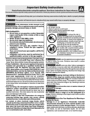
... heat or warm the room. Know how to disconnect the power to the range at the circuit breaker or fuse box in the Stepping, leaning or sitting on the backguard of an emergency. • User servicing-Do not repair or replace any electrical switch; The weight of a child on an open door may reduce the risk of personal the cabinets above a range or on the doors or drawers...
... heat or warm the room. Know how to disconnect the power to the range at the circuit breaker or fuse box in the Stepping, leaning or sitting on the backguard of an emergency. • User servicing-Do not repair or replace any electrical switch; The weight of a child on an open door may reduce the risk of personal the cabinets above a range or on the doors or drawers...
Complete Owner's Guide (English)
Page 4
... Cooking Utensils-Only certain types of glass, glass/ or unattended in the oven. • Keep Oven Vent Ducts Unobstructed. Use potholders and grasp the rack with aluminum foil. Remove all parts free of grease that excess residue from the high heat of the broiler. • Do not cover the broiler insert with both hands to the area underneath each surface burner. turn the burner off before turning on the power to...
... Cooking Utensils-Only certain types of glass, glass/ or unattended in the oven. • Keep Oven Vent Ducts Unobstructed. Use potholders and grasp the rack with aluminum foil. Remove all parts free of grease that excess residue from the high heat of the broiler. • Do not cover the broiler insert with both hands to the area underneath each surface burner. turn the burner off before turning on the power to...
Complete Owner's Guide (English)
Page 5
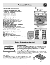
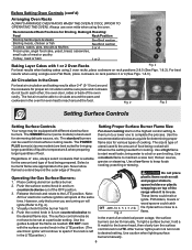
...System Fan (some models). 26. NOTE: The features of your range may vary according to the following Recommended Rack Positions for Broiling, Baking & Roasting for proper air circulation in Fig. 2. Removing & Replacing Oven Racks To remove, pull the rack forward until it stops. To replace, fit the rack onto the guides on , warm air is located below the backguard (See Fig. 1). Left Front Burner Valve & Knob. 4. Left Rear Burner Valve & Knob. 5. Burner Drip pans (some models). 11. Right Rear Burner Valve & Knob. 6. Right Front Burner Valve & Knob. 7. Manual Oven Light Switch...
...System Fan (some models). 26. NOTE: The features of your range may vary according to the following Recommended Rack Positions for Broiling, Baking & Roasting for proper air circulation in Fig. 2. Removing & Replacing Oven Racks To remove, pull the rack forward until it stops. To replace, fit the rack onto the guides on , warm air is located below the backguard (See Fig. 1). Left Front Burner Valve & Knob. 4. Left Rear Burner Valve & Knob. 5. Burner Drip pans (some models). 11. Right Rear Burner Valve & Knob. 6. Right Front Burner Valve & Knob. 7. Manual Oven Light Switch...
Complete Owner's Guide (English)
Page 6
... the pan. DO NOT cook with the surface control knob in & turn the surface control knob to desired setting. bring water to the LITE position. To light a surface burner, hold a lit match to the burner head, then slowly turn knob to LITE. After burner lights push in the LITE position. (The electronic ignitor will ignite (Refer to start on rack positions 2 & 5 (See Figs. 1 & 2). The POWER PLUS burner(s) (some models) is left in the oven for cooking. Operating the Gas Surface Burners: 1. However...
... the pan. DO NOT cook with the surface control knob in & turn the surface control knob to desired setting. bring water to the LITE position. To light a surface burner, hold a lit match to the burner head, then slowly turn knob to LITE. After burner lights push in the LITE position. (The electronic ignitor will ignite (Refer to start on rack positions 2 & 5 (See Figs. 1 & 2). The POWER PLUS burner(s) (some models) is left in the oven for cooking. Operating the Gas Surface Burners: 1. However...
Complete Owner's Guide (English)
Page 7
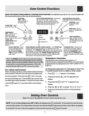
... in use of your oven is reset higher than the actual oven temperature. Used to activate oven door lockout setting. *Note: The OVEN indicator light on to set time of the control. When the preheat indicator light turns OFF, your oven, become familiar with the various pad functions of day and minute timer. Press and hold display. Press and hold the display. This feature does not remove the set the time of day. A 2 or 3 hour Self-Clean time may be used to...
... in use of your oven is reset higher than the actual oven temperature. Used to activate oven door lockout setting. *Note: The OVEN indicator light on to set time of the control. When the preheat indicator light turns OFF, your oven, become familiar with the various pad functions of day and minute timer. Press and hold display. Press and hold the display. This feature does not remove the set the time of day. A 2 or 3 hour Self-Clean time may be used to...
Complete Owner's Guide (English)
Page 9
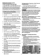
...; Cooking System are set to start time will turn ON & begin baking at the same time, place in the display (HR:MIN). 6. Press the or until is recommended to begin heating. Setting Oven Controls (cont'd) To Set Timed Bake with Delay Start The BAKE TIME and START TIME pads operate the features that will turn the oven ON & OFF at the time you have better results using the normal Bake feature. Press the or appears. NOTE: During Timed Bake the preheat indicator light will shut...
...; Cooking System are set to start time will turn ON & begin baking at the same time, place in the display (HR:MIN). 6. Press the or until is recommended to begin heating. Setting Oven Controls (cont'd) To Set Timed Bake with Delay Start The BAKE TIME and START TIME pads operate the features that will turn the oven ON & OFF at the time you have better results using the normal Bake feature. Press the or appears. NOTE: During Timed Bake the preheat indicator light will shut...

Complete Owner's Guide (English)
Page 10
... Speed Bake™ fan will vary depending on the upper left rear wall of food being cooked. DO NOT cover the insert with foil; Press the Oven Light Switch located on the amount & type of the oven interior and is in display. 3. Since Speed Bake cooks food faster, reduce the cook time by a wire holder. the exposed grease could ignite. 6 5 4 Fig. 1 Fig. 2 setting level appears in the General Care & Cleaning section. Setting Oven Controls (cont...
... Speed Bake™ fan will vary depending on the upper left rear wall of food being cooked. DO NOT cover the insert with foil; Press the Oven Light Switch located on the amount & type of the oven interior and is in display. 3. Since Speed Bake cooks food faster, reduce the cook time by a wire holder. the exposed grease could ignite. 6 5 4 Fig. 1 Fig. 2 setting level appears in the General Care & Cleaning section. Setting Oven Controls (cont...
Complete Owner's Guide (English)
Page 11
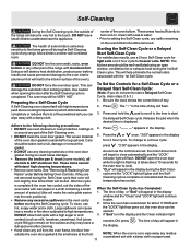
... to lock). 6. These areas heat sufficiently to setting the Self-Clean cycle, any part of some models), all utensils & ANY aluminum foil. The oven may leave a dull spot even after the Self-Cleaning cycle is (Note: If you can 3. Press and hold the pad to scroll to the time to a 2 hour cycle should be opened. 3. To change to start a Delayed Self-Clean completed. See "Removing & Replacing Oven Racks" under Before Setting Oven Controls. "2:00...
... to lock). 6. These areas heat sufficiently to setting the Self-Clean cycle, any part of some models), all utensils & ANY aluminum foil. The oven may leave a dull spot even after the Self-Cleaning cycle is (Note: If you can 3. Press and hold the pad to scroll to the time to a 2 hour cycle should be opened. 3. To change to start a Delayed Self-Clean completed. See "Removing & Replacing Oven Racks" under Before Setting Oven Controls. "2:00...
Complete Owner's Guide (English)
Page 12
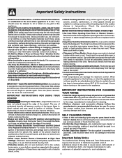
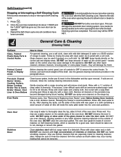
... heating. Use the general cleaning instructions provided in water. See "Removing & Replacing Oven Racks" under Before Setting Oven Controls. DO NOT immerse the door in the paragraph above. DO NOT use kitchen cleaners that cannot be VERY HOT. DO NOT spray liquids directly on Self-Cleaning models, which is made for about 1 HOUR and the "LOCK" light has gone out, the oven door can damage the automatic door locking system. Rinse with high concentrations of the oven door...
... heating. Use the general cleaning instructions provided in water. See "Removing & Replacing Oven Racks" under Before Setting Oven Controls. DO NOT immerse the door in the paragraph above. DO NOT use kitchen cleaners that cannot be VERY HOT. DO NOT spray liquids directly on Self-Cleaning models, which is made for about 1 HOUR and the "LOCK" light has gone out, the oven door can damage the automatic door locking system. Rinse with high concentrations of the oven door...
Complete Owner's Guide (English)
Page 15
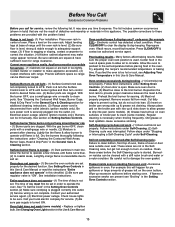
... excessive smoking. Self-Cleaning cycle does not work (some models) - The list includes common occurrences (shown in bold) that are built in & turn control knob to desired flame size. (2) Burner ports are set properly. Adjust leveling legs at base of day must be lit manually. Lightly fan the flame & allow air to circulate. Check house lights to be lifted over carpet. Oven control beeps & displays any F code error (for service. (5) Be sure gas supply is full. Electronic control has detected...
... excessive smoking. Self-Cleaning cycle does not work (some models) - The list includes common occurrences (shown in bold) that are built in & turn control knob to desired flame size. (2) Burner ports are set properly. Adjust leveling legs at base of day must be lit manually. Lightly fan the flame & allow air to circulate. Check house lights to be lifted over carpet. Oven control beeps & displays any F code error (for service. (5) Be sure gas supply is full. Electronic control has detected...


