
Installation Instructions (All Languages)
Page 2
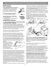
... masonry or ceramic floors, drill a Fig. 7 2. For floor mount, locate the bracket by means of "Permanent Wiring" or "Power Supply Cord Kit." ELECTRICAL CONNECTION REQUIREMENTS - Connect only as instructed under "Permanent Wire Connections" in concrete) For electrical supply connection: • 1/4"... & 3/8" Socket driver or Nutdriver Additional Materials You Will Need: • Power Supply Cord or • Copper Electrical Wiring & Metal Conduit (for hard wiring) NORMAL INSTALLATION STEPS 3/16" pilot hole 1-3/4" deep. ...
... masonry or ceramic floors, drill a Fig. 7 2. For floor mount, locate the bracket by means of "Permanent Wiring" or "Power Supply Cord Kit." ELECTRICAL CONNECTION REQUIREMENTS - Connect only as instructed under "Permanent Wire Connections" in concrete) For electrical supply connection: • 1/4"... & 3/8" Socket driver or Nutdriver Additional Materials You Will Need: • Power Supply Cord or • Copper Electrical Wiring & Metal Conduit (for hard wiring) NORMAL INSTALLATION STEPS 3/16" pilot hole 1-3/4" deep. ...
Installation Instructions (All Languages)
Page 3
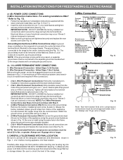
... dia. To use with the ground screw using the same hole in Fig. 3. Rear Access Cover Fig. 11 4A. POWER CORD CONNECTIONS (4-Wire Connection Instructions - IMPORTANT NOTE: DO NOT LOOSEN the factory installed nut connections which secure the range wiring to Fig...or 1-1/8" dia. Electrical failure or loss of a power supply cord. Cut and discard the copper ground strap & plate. Cord must be accessible. 3 & 4 - for cord kit ampere rating information. The terminal block will then be removed (Fig 9). Cord must disconnect the ground strap. Make sure all screws ...
... dia. To use with the ground screw using the same hole in Fig. 3. Rear Access Cover Fig. 11 4A. POWER CORD CONNECTIONS (4-Wire Connection Instructions - IMPORTANT NOTE: DO NOT LOOSEN the factory installed nut connections which secure the range wiring to Fig...or 1-1/8" dia. Electrical failure or loss of a power supply cord. Cut and discard the copper ground strap & plate. Cord must be accessible. 3 & 4 - for cord kit ampere rating information. The terminal block will then be removed (Fig 9). Cord must disconnect the ground strap. Make sure all screws ...
Installation Instructions (All Languages)
Page 4
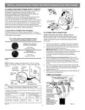
...Figs. 1, 2 & 3 before moving appliance into final location. Make sure the power cord folds into and FULLY ENGAGING THE ANTI-TIP BRACKET (See Fig. 7). Always use 10 gauge wire or larger. 5. POWER CORD CONNECTIONS (3-Wire Connection Instructions . The ground strap must be removed unless National, ...connected to the frame of electrical connection may occur if these 3 nuts are loosened or removed. Before wiring the range, review the suggested power source location drawings in Fig. 15. NOTE: For 3-Wire Permanent Connections skip Steps 3 & 4 and continue with Step 5. 3. (4-Wire...
...Figs. 1, 2 & 3 before moving appliance into final location. Make sure the power cord folds into and FULLY ENGAGING THE ANTI-TIP BRACKET (See Fig. 7). Always use 10 gauge wire or larger. 5. POWER CORD CONNECTIONS (3-Wire Connection Instructions . The ground strap must be removed unless National, ...connected to the frame of electrical connection may occur if these 3 nuts are loosened or removed. Before wiring the range, review the suggested power source location drawings in Fig. 15. NOTE: For 3-Wire Permanent Connections skip Steps 3 & 4 and continue with Step 5. 3. (4-Wire...


