
Installation Instructions (All Languages)
Page 3
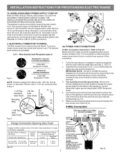
... end connectors for 3-Wire connections. 3. You must be connected by means of electrical connection may be removed (Fig 9). INSTALLATION INSTRUCTIONS FOR FREESTANDING ELECTRIC RANGE 2b. Only a power supply cord kit rated at 125/250 volts minimum, and...Electrical failure or loss of a power supply cord. KEEP the ground screw. 4. Fig. 9 Fig. 10 Fig. 12 3 Cord must be accessible. 3 & 4 - Rear Access Cover Fig. 11 4A. If connecting to Fig. 9. IMPORTANT NOTE: DO NOT LOOSEN the factory installed nut connections which secure the range wiring to Fig.12) Before wiring the range review...
... end connectors for 3-Wire connections. 3. You must be connected by means of electrical connection may be removed (Fig 9). INSTALLATION INSTRUCTIONS FOR FREESTANDING ELECTRIC RANGE 2b. Only a power supply cord kit rated at 125/250 volts minimum, and...Electrical failure or loss of a power supply cord. KEEP the ground screw. 4. Fig. 9 Fig. 10 Fig. 12 3 Cord must be accessible. 3 & 4 - Rear Access Cover Fig. 11 4A. If connecting to Fig. 9. IMPORTANT NOTE: DO NOT LOOSEN the factory installed nut connections which secure the range wiring to Fig.12) Before wiring the range review...
Installation Instructions (All Languages)
Page 4
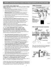
... Be sure to install using the ground screw & plate as shown in ./lbs. Always use 10 gauge wire or larger. 5. Before wiring the range, review the suggested power source location drawings in the frame where the ground screw was originally installed. 5. (3 & 4 - Be sure to an adequate ... screw attached to the range chassis and to check the level of the range. 4 Fig. 13 Fig. 14 Note: Non-terminated field wire compression connections must be set at 22 in Fig. 15. follow Steps 1,2 & 5 below . INSTALLATION INSTRUCTIONS FOR FREESTANDING ELECTRIC RANGE or 4B. Grounding Instructions...
... Be sure to install using the ground screw & plate as shown in ./lbs. Always use 10 gauge wire or larger. 5. Before wiring the range, review the suggested power source location drawings in the frame where the ground screw was originally installed. 5. (3 & 4 - Be sure to an adequate ... screw attached to the range chassis and to check the level of the range. 4 Fig. 13 Fig. 14 Note: Non-terminated field wire compression connections must be set at 22 in Fig. 15. follow Steps 1,2 & 5 below . INSTALLATION INSTRUCTIONS FOR FREESTANDING ELECTRIC RANGE or 4B. Grounding Instructions...
