English Manual.
Page 6
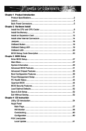
...Internal Connectors 14 Jumpers 18 OnBoard Button 19 OnBoard Debug LED 19 OnBoard LED 20 BIOS Debug Code Description 20 Chapter 3 BIOS Setup Enter BIOS Setup 27 Main Menu 27 System Information 29 Advanced BIOS Features 31 Advanced Chipset Features 35 Boot Configuration Features 39 Power Management Setup 41 PC... Health Status 43 Quantum BIOS 44 BIOS Security Features 51 Load Optimal Defaults 52 Save & Exit Setup 52 Exit Without Saving 52 Chapter 4 CD Instruction Utility CD ...
...Internal Connectors 14 Jumpers 18 OnBoard Button 19 OnBoard Debug LED 19 OnBoard LED 20 BIOS Debug Code Description 20 Chapter 3 BIOS Setup Enter BIOS Setup 27 Main Menu 27 System Information 29 Advanced BIOS Features 31 Advanced Chipset Features 35 Boot Configuration Features 39 Power Management Setup 41 PC... Health Status 43 Quantum BIOS 44 BIOS Security Features 51 Load Optimal Defaults 52 Save & Exit Setup 52 Exit Without Saving 52 Chapter 4 CD Instruction Utility CD ...
English Manual.
Page 7
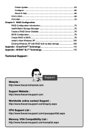
... LOGO 69 FOX DMI 70 Chapter 5 RAID Configuration RAID Configuration Introduction 73 Intel® Matrix Storage Manager 75 Create a RAID Driver Diskette 76 BIOS Configuration 78 Create RAID in BIOS 78 Install a New Windows XP 105 Existing Windows XP with RAID built as data storage 109 Appendix - NVIDIA® SLI™ Technology...
... LOGO 69 FOX DMI 70 Chapter 5 RAID Configuration RAID Configuration Introduction 73 Intel® Matrix Storage Manager 75 Create a RAID Driver Diskette 76 BIOS Configuration 78 Create RAID in BIOS 78 Install a New Windows XP 105 Existing Windows XP with RAID built as data storage 109 Appendix - NVIDIA® SLI™ Technology...
English Manual.
Page 14
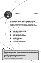
... ■ Install the Memory ■ Install an Expansion Card ■ Install other Internal Connectors ■ Onboard Button ■ Onboard Debug LED ■ Onboard LED ■ BIOS Debug Code Description Please visit the following website for more supporting information about your motherboard. CPU Support List: http://www.foxconnsupport.com/cpusupportlist.aspx Memory...
... ■ Install the Memory ■ Install an Expansion Card ■ Install other Internal Connectors ■ Onboard Button ■ Onboard Debug LED ■ Onboard LED ■ BIOS Debug Code Description Please visit the following website for more supporting information about your motherboard. CPU Support List: http://www.foxconnsupport.com/cpusupportlist.aspx Memory...
English Manual.
Page 15
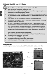
The CPU cannot be set the frequency beyond hardware specifications since it does not meet the standard requirements for HT Technology ■ A BIOS that supports HT Technology and has it enabled Install the CPU Locate the alignment keys on the motherboard CPU socket and the notches on the ...
The CPU cannot be set the frequency beyond hardware specifications since it does not meet the standard requirements for HT Technology ■ A BIOS that supports HT Technology and has it enabled Install the CPU Locate the alignment keys on the motherboard CPU socket and the notches on the ...
English Manual.
Page 18
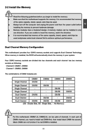
... Configuration This motherboard provides four DDR3 memory sockets and supports Dual Channel Technology. A memory module can not function if no red DIMM is installed, the BIOS will automatically check the memory in only one direction. DS/SS Dual Channel DS/SS - In each channel has two memory sockets as following guidelines...
... Configuration This motherboard provides four DDR3 memory sockets and supports Dual Channel Technology. A memory module can not function if no red DIMM is installed, the BIOS will automatically check the memory in only one direction. DS/SS Dual Channel DS/SS - In each channel has two memory sockets as following guidelines...
English Manual.
Page 20
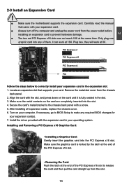
... card and then pull the card straight up from the slot. 13 13 Locate an expansion slot that came with a screw. 5. If necessary, go to BIOS Setup to the chassis back panel with your card. Only plug one graphic card into the PCI Express x16 slot. After installing all expansion cards... from the chassis back panel. 2. Installing and Removing a PCI Express x16 Graphics Card: • Installing a Graphics Card: Gently insert the graphics card into any required BIOS changes for your expansion card in the slot. 3.
... card and then pull the card straight up from the slot. 13 13 Locate an expansion slot that came with a screw. 5. If necessary, go to BIOS Setup to the chassis back panel with your card. Only plug one graphic card into the PCI Express x16 slot. After installing all expansion cards... from the chassis back panel. 2. Installing and Removing a PCI Express x16 Graphics Card: • Installing a Graphics Card: Gently insert the graphics card into any required BIOS changes for your expansion card in the slot. 3.
English Manual.
Page 23
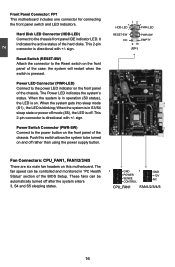
It indicates the active status of the BIOS Setup. sign. This 2-pin connector is directional with +/- sign. RESET-SW PWR-SW NC EMPTY 9 10 FP1 Fan Connectors: CPU_FAN1, FAN1/2/3/4/5 There are six main ...
It indicates the active status of the BIOS Setup. sign. This 2-pin connector is directional with +/- sign. RESET-SW PWR-SW NC EMPTY 9 10 FP1 Fan Connectors: CPU_FAN1, FAN1/2/3/4/5 There are six main ...
English Manual.
Page 25
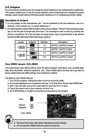
"Closed" means placing a jumper cap on the two pins to store the basic hardware information (such as a screwdriver) onto pins 1-2 to factory default when the BIOS settings were mistakenly modified. Jumper 1 1 Diagram 1 1 1 1 Definition 1-2 1-2 1-2 2-3 Description Set Pin 1 and Pin 2 closed Set Pin 1 and Pin 2 ... any jumper setting. The shorting can also be identified by changing the jumper settings. This will clear CMOS data. 3. Go to BIOS Setup to your computer and turn it . The following content carefully prior to modify them . It can prevent hazardous ESD (Electrical...
"Closed" means placing a jumper cap on the two pins to store the basic hardware information (such as a screwdriver) onto pins 1-2 to factory default when the BIOS settings were mistakenly modified. Jumper 1 1 Diagram 1 1 1 1 Definition 1-2 1-2 1-2 2-3 Description Set Pin 1 and Pin 2 closed Set Pin 1 and Pin 2 ... any jumper setting. The shorting can also be identified by changing the jumper settings. This will clear CMOS data. 3. Go to BIOS Setup to your computer and turn it . The following content carefully prior to modify them . It can prevent hazardous ESD (Electrical...
English Manual.
Page 27
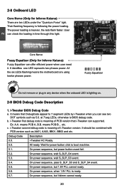
... and etc. On power sequence, wait S_SLP_S4 event. 5.3. 2-8 OnBoard LED Core Nerve (Only for Inferno Katana): Fuzzy Equalizer can offer efficient power when user need it. Their flashing frequency is ready. 5.7. The power loading is lighting on. 2-9 BIOS Debug Code Description 1. All the six LEDs flashing means the motherboard are ten LEDs under...
... and etc. On power sequence, wait S_SLP_S4 event. 5.3. 2-8 OnBoard LED Core Nerve (Only for Inferno Katana): Fuzzy Equalizer can offer efficient power when user need it. Their flashing frequency is ready. 5.7. The power loading is lighting on. 2-9 BIOS Debug Code Description 1. All the six LEDs flashing means the motherboard are ten LEDs under...
English Manual.
Page 28
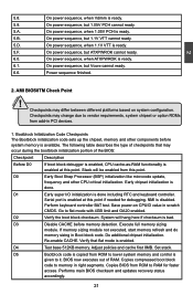
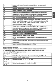
...mode is enabled. Perform keyboard controller BAT test. Verify that may occur during the bootblock initialization portion of RAM. Performs main BIOS checksum and updates recovery status accordingly. 21 21 Checkpoints may change due to vendor requirements, system chipset or option ROMs from this...-RAM functionality is given to RAM for debugging. On power sequence, but Vcore cannot ready. 6.6. NMI is ready. 5.B. Copies BIOS from ROM to lower system memory and control is enabled at this point if needed for faster access. System will be enabled from...
...mode is enabled. Perform keyboard controller BAT test. Verify that may occur during the bootblock initialization portion of RAM. Performs main BIOS checksum and updates recovery status accordingly. 21 21 Checkpoints may change due to vendor requirements, system chipset or option ROMs from this...-RAM functionality is given to RAM for debugging. On power sequence, but Vcore cannot ready. 6.6. NMI is ready. 5.B. Copies BIOS from ROM to lower system memory and control is enabled at this point if needed for faster access. System will be enabled from...

English Manual.
Page 29
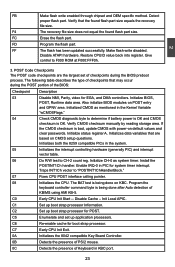
... flows to checkpoint E0. E9 Set up floppy controller and data. EA Enable ATAPI hardware. Jump back to execute serial flash. If BIOS recovery is reserved for chipset vendors & system manufacturers. Leaves all RAM below 1MB Read-Write including E000 and F000 shadow areas but closing...2. 2 D6 D7 D8 D9 DA DC E1-E8 EC-EE Both key sequence and OEM specific method is checked to determine if BIOS recovery is uncompressed into memory. See Bootblock Recovery Code Checkpoints section of document for more information. Determine whether to checkpoint EB. The Runtime...
... flows to checkpoint E0. E9 Set up floppy controller and data. EA Enable ATAPI hardware. Jump back to execute serial flash. If BIOS recovery is reserved for chipset vendors & system manufacturers. Leaves all RAM below 1MB Read-Write including E000 and F000 shadow areas but closing...2. 2 D6 D7 D8 D9 DA DC E1-E8 EC-EE Both key sequence and OEM specific method is checked to determine if BIOS recovery is uncompressed into memory. See Bootblock Recovery Code Checkpoints section of document for more information. Determine whether to checkpoint EB. The Runtime...
English Manual.
Page 30
... the recovery file size. FD Program the flash part. POST Code Checkpoints The POST code checkpoints are based on KBC. Also initialize BIOS modules on default values and clear passwords. Verify CMOS checksum manually by reading storage area. Initialize CH-0 as mentioned in the system..... 0B Detects the presence of PS/2 mouse. 0C Detects the presence of KB/MS using AMI KB-5. Detect proper flash part. Initialize BIOS, POST, Runtime data area. Initialize status register A. Initializes both the 8259 compatible PICs in the Kernel Variable "wCMOSFlags." 04 Check CMOS ...
... the recovery file size. FD Program the flash part. POST Code Checkpoints The POST code checkpoints are based on KBC. Also initialize BIOS modules on default values and clear passwords. Verify CMOS checksum manually by reading storage area. Initialize CH-0 as mentioned in the system..... 0B Detects the presence of PS/2 mouse. 0C Detects the presence of KB/MS using AMI KB-5. Detect proper flash part. Initialize BIOS, POST, Runtime data area. Initialize status register A. Initializes both the 8259 compatible PICs in the Kernel Variable "wCMOSFlags." 04 Check CMOS ...

English Manual.
Page 31
... ADM module and uncompress it. Detects and initializes the video adapter installed in the system. 24 Uncompress and initialize any platform specific BIOS modules. Set the window for displaying text information. 37 Displaying sign-on message, CPU information, setup key message, and any kind...status and programs the KBD typematic rate. 75 Initialize Int-13 and prepare for IPL detection. 78 Initializes IPL devices controlled by BIOS and option ROMs. 7C Generate and write contents of implementation that the POST INT09h handler gets control for IRQ1. etc.) successfully ...
... ADM module and uncompress it. Detects and initializes the video adapter installed in the system. 24 Uncompress and initialize any platform specific BIOS modules. Set the window for displaying text information. 37 Displaying sign-on message, CPU information, setup key message, and any kind...status and programs the KBD typematic rate. 75 Initialize Int-13 and prepare for IPL detection. 78 Initializes IPL devices controlled by BIOS and option ROMs. 7C Generate and write contents of implementation that the POST INT09h handler gets control for IRQ1. etc.) successfully ...
English Manual.
Page 32
2 87 Execute BIOS setup if needed . Check boot password if installed. 8C Late POST initialization of the MTRR's. Please note this checkpoint comes right after checkpoint 20h A1 ... interrupt by invoking all handlers. AA Uninstall POST INT1Ch vector and INT09h vector. A7 Displays the system configuration screen if enabled. Prepare CPU for different BIOS modules. Enable/Disable NMI as selected 90 Initialization of runtime image preparation for OS boot including final MTRR values. 00 Passes control to OS.
2 87 Execute BIOS setup if needed . Check boot password if installed. 8C Late POST initialization of the MTRR's. Please note this checkpoint comes right after checkpoint 20h A1 ... interrupt by invoking all handlers. AA Uninstall POST INT1Ch vector and INT09h vector. A7 Displays the system configuration screen if enabled. Prepare CPU for different BIOS modules. Enable/Disable NMI as selected 90 Initialization of runtime image preparation for OS boot including final MTRR values. 00 Passes control to OS.
English Manual.
Page 33
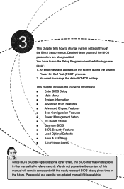
...; Boot Configuration Features ■ Power Management Setup ■ PC Health Status ■ Quantum BIOS ■ BIOS Security Features ■ Load Optimal Defaults ■ Save & Exit Setup ■ Exit Without Saving Since BIOS could be updated some other times, the BIOS information described in the future. This chapter tells how to change the default CMOS...
...; Boot Configuration Features ■ Power Management Setup ■ PC Health Status ■ Quantum BIOS ■ BIOS Security Features ■ Load Optimal Defaults ■ Save & Exit Setup ■ Exit Without Saving Since BIOS could be updated some other times, the BIOS information described in the future. This chapter tells how to change the default CMOS...

English Manual.
Page 34
... POST screen, DEL to enter Setup. ! v02.67 (C) Copyright 1985-2009, American Megatrends, Inc. ► System Information It displays the basic system configuration, such as BIOS ID, CPU information, memory size and system date, time. Use the arrow keys to select a specific item and press to go to maintain optimal system... main menu is critical to the sub-menu. We do not suggest that you can be set up through this menu. Each item in the BIOS Setup, and we shall not be responsible for any damage which resulted from a list of the screen, you change you made. They all can be...
... POST screen, DEL to enter Setup. ! v02.67 (C) Copyright 1985-2009, American Megatrends, Inc. ► System Information It displays the basic system configuration, such as BIOS ID, CPU information, memory size and system date, time. Use the arrow keys to select a specific item and press to go to maintain optimal system... main menu is critical to the sub-menu. We do not suggest that you can be set up through this menu. Each item in the BIOS Setup, and we shall not be responsible for any damage which resulted from a list of the screen, you change you made. They all can be...
English Manual.
Page 35
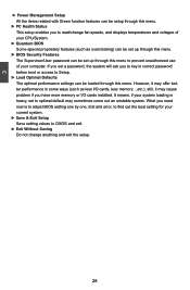
... password before boot or access to Setup. ► Load Optimal Defaults The optimal performance settings can be set up through this menu. ► BIOS Security Features The Supervisor/User password can be loaded through this menu. However, it may cause problem if you need now is heavy, set to...set up through this menu to prevent unauthorized use of your CPU/System. ► Quantum BIOS Some special proprietary features (such as less I /O cards installed. It means, if your system loading is to adjust BIOS setting one by one, trial and error, to find out the best setting for your ...
... password before boot or access to Setup. ► Load Optimal Defaults The optimal performance settings can be set up through this menu. ► BIOS Security Features The Supervisor/User password can be loaded through this menu. However, it may cause problem if you need now is heavy, set to...set up through this menu to prevent unauthorized use of your CPU/System. ► Quantum BIOS Some special proprietary features (such as less I /O cards installed. It means, if your system loading is to adjust BIOS setting one by one, trial and error, to find out the best setting for your ...

English Manual.
Page 36
... system time. System Information System Overview Help Item System Time 00:50:11 System Date Tue 07/21/2009 AMIBIOS BIOS Version :08.00.15 BIOS Bulid Date :07/21/09 BIOS ID :934F1D06 Processor Use [ENTER], [TAB] or [SHIFT-TAB] to set up /down keys to select an... is automatically displayed by users. System Information This sub-menu is used to select a field. Month-month from Sun. Year-year, set up the standard BIOS features, such as the date, time, memory and so on. Use [+] or [-] to 12. Copyright (C) 1985-2009, American Megatrends, Inc. Speed Count ...
... system time. System Information System Overview Help Item System Time 00:50:11 System Date Tue 07/21/2009 AMIBIOS BIOS Version :08.00.15 BIOS Bulid Date :07/21/09 BIOS ID :934F1D06 Processor Use [ENTER], [TAB] or [SHIFT-TAB] to set up /down keys to select an... is automatically displayed by users. System Information This sub-menu is used to select a field. Month-month from Sun. Year-year, set up the standard BIOS features, such as the date, time, memory and so on. Use [+] or [-] to 12. Copyright (C) 1985-2009, American Megatrends, Inc. Speed Count ...
English Manual.
Page 38
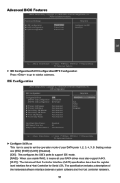
Advanced BIOS Features Advanced Settings Help Item ► IDE configuration ► AHCI Configuration ► MPS Configuration PPrreessss EEnntteerr Press Enter Press Enter Configure the IDE device...the operation mode of the hardware/software interface between system software and the host controller hardware. 31 Copyright (C) 1985-2009, American Megatrends, Inc. Advanced BIOS Features CMOS Setup Utility - IDE Configuration IDE Configuration Help Item Configure SATA as IIDDEE SATA#1 IDE Configuration Compatible SATA#2 IDE Configuration Enhanced ► ...
Advanced BIOS Features Advanced Settings Help Item ► IDE configuration ► AHCI Configuration ► MPS Configuration PPrreessss EEnntteerr Press Enter Press Enter Configure the IDE device...the operation mode of the hardware/software interface between system software and the host controller hardware. 31 Copyright (C) 1985-2009, American Megatrends, Inc. Advanced BIOS Features CMOS Setup Utility - IDE Configuration IDE Configuration Help Item Configure SATA as IIDDEE SATA#1 IDE Configuration Compatible SATA#2 IDE Configuration Enhanced ► ...
English Manual.
Page 39
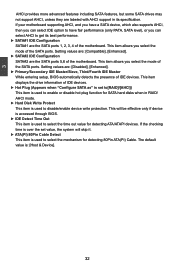
...► Hot Plug (Appears when "Configure SATA as" is set value, the system will be effective only if device is accessed through BIOS. ► IDE Detect Time Out This item is used to enable or disable hot plug function for detecting 80Pin ATA(PI) Cable....► SATA#2 IDE Configuration SATA#2 are : [Disabled], [Enhanced]. ► Primary/Secondary IDE Master/Slave, Third/Fourth IDE Master While entering setup, BIOS automatically detects the presence of the motherboard. 3 AHCI provides more advanced features including SATA features, but some SATA drives may not support AHCI, unless they...
...► Hot Plug (Appears when "Configure SATA as" is set value, the system will be effective only if device is accessed through BIOS. ► IDE Detect Time Out This item is used to enable or disable hot plug function for detecting 80Pin ATA(PI) Cable....► SATA#2 IDE Configuration SATA#2 are : [Disabled], [Enhanced]. ► Primary/Secondary IDE Master/Slave, Third/Fourth IDE Master While entering setup, BIOS automatically detects the presence of the motherboard. 3 AHCI provides more advanced features including SATA features, but some SATA drives may not support AHCI, unless they...


