English Manual.
Page 2
... use motherboard better, and tells you how to use of this symbol indicates that can help prevent potential negative consequences for specific features. All trade names are registered trademarks of their respective owners. P/N: 3A221LA00-000-G Symbol description: ! By ensuring this...this product. More information: If you purchased this manual may not be caused by inappropriate waste handling of Foxconn, Inc. Version: User's Manual V1.0 for G41MX 2.0 Series motherboard. Caution: refers to the physical motherboard for the environment and human health, which could ...
... use motherboard better, and tells you how to use of this symbol indicates that can help prevent potential negative consequences for specific features. All trade names are registered trademarks of their respective owners. P/N: 3A221LA00-000-G Symbol description: ! By ensuring this...this product. More information: If you purchased this manual may not be caused by inappropriate waste handling of Foxconn, Inc. Version: User's Manual V1.0 for G41MX 2.0 Series motherboard. Caution: refers to the physical motherboard for the environment and human health, which could ...

English Manual.
Page 3
... 61000-3-2/:2000 Electromagnetic compatibility (EMC) Part 3: Limits Section 2: Limits for harmonic current emissions (equipment input current declares that the product Motherboard G41MX 2.0/G41MX-K 2.0/G41MX-F 2.0 is in conformity with (reference to the specification under which conformity is declared in accordance with 89/336 EEC-EMC Directive) ■ EN 55022: 1998/A2: 2003 Limits and methods...
... 61000-3-2/:2000 Electromagnetic compatibility (EMC) Part 3: Limits Section 2: Limits for harmonic current emissions (equipment input current declares that the product Motherboard G41MX 2.0/G41MX-K 2.0/G41MX-F 2.0 is in conformity with (reference to the specification under which conformity is declared in accordance with 89/336 EEC-EMC Directive) ■ EN 55022: 1998/A2: 2003 Limits and methods...
English Manual.
Page 6
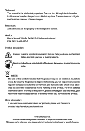
Table of Contents Chapter 1 Product Introduction Product Specifications 2 Layout...4 Back Panel Connectors 5 Chapter 2 Hardware Install Install the CPU and CPU Cooler 8 Install the Memory 11 Install an Expansion Card 13 Install other Internal ...
Table of Contents Chapter 1 Product Introduction Product Specifications 2 Layout...4 Back Panel Connectors 5 Chapter 2 Hardware Install Install the CPU and CPU Cooler 8 Install the Memory 11 Install an Expansion Card 13 Install other Internal ...

English Manual.
Page 8
With advanced overclocking capability and a range of connectivity features for today multi-media computing requirements, G41MX 2.0/G41MX-K 2.0/G41MX-F 2.0 enables you for break-through performance. This chapter includes the following information: ■ Product Specifications ■ Layout ■ Back Panel Connectors Thank you to maximize computing power, providing only what you need for buying Foxconn G41MX 2.0 Series motherboard. Foxconn products are engineered to unleash more power from your computer.
With advanced overclocking capability and a range of connectivity features for today multi-media computing requirements, G41MX 2.0/G41MX-K 2.0/G41MX-F 2.0 enables you for break-through performance. This chapter includes the following information: ■ Product Specifications ■ Layout ■ Back Panel Connectors Thank you to maximize computing power, providing only what you need for buying Foxconn G41MX 2.0 Series motherboard. Foxconn products are engineered to unleash more power from your computer.
English Manual.
Page 9
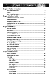
1 1-1 Product Specifications CPU Support LGA775 socket Intel® CPU: CoreTM 2 Quad / CoreTM 2 Duo / Pentium® Dual-Core / Celeron® Dual-Core / Conroe-L processors Supports 45nm processor Front ...; ICH7 Memory 2 x 240-pin DDR2 DIMM sockets Support up to 8GB of system memory Dual channel DDR2 800/667MHz architecture Audio Realtek 6-channel audio chip (G41MX 2.0/G41MX-F 2.0) Realtek 8-channel audio chip (G41MX-K 2.0) High Definition Audio 2/4/5.1/7.1-channel Support for S/PDIF out Support Jack-Sensing function LAN Realtek 10/100Mb/s LAN chip...
1 1-1 Product Specifications CPU Support LGA775 socket Intel® CPU: CoreTM 2 Quad / CoreTM 2 Duo / Pentium® Dual-Core / Celeron® Dual-Core / Conroe-L processors Supports 45nm processor Front ...; ICH7 Memory 2 x 240-pin DDR2 DIMM sockets Support up to 8GB of system memory Dual channel DDR2 800/667MHz architecture Audio Realtek 6-channel audio chip (G41MX 2.0/G41MX-F 2.0) Realtek 8-channel audio chip (G41MX-K 2.0) High Definition Audio 2/4/5.1/7.1-channel Support for S/PDIF out Support Jack-Sensing function LAN Realtek 10/100Mb/s LAN chip...

English Manual.
Page 12
USB Ports The USB port supports the USB 2.0/1.1 specification. PS/2 Mouse Port Use the upper port (green) to this port for G41MX-K 2.0) The DVI-D port supports DVI-D specification. VGA Port To connect with external display devices, such as an USB keyboard/mouse, USB printer, USB flash... drive and etc. 7. 1 1-3 Back Panel Connectors Back Panel of G41MX-K 2.0: PS/2 Mouse Port VGA Port ...
USB Ports The USB port supports the USB 2.0/1.1 specification. PS/2 Mouse Port Use the upper port (green) to this port for G41MX-K 2.0) The DVI-D port supports DVI-D specification. VGA Port To connect with external display devices, such as an USB keyboard/mouse, USB printer, USB flash... drive and etc. 7. 1 1-3 Back Panel Connectors Back Panel of G41MX-K 2.0: PS/2 Mouse Port VGA Port ...

English Manual.
Page 15
...9632; An operating system that is not recommended that the system bus frequency be inserted if oriented incorrectly. (Or you begin to your hardware specifications including the CPU, graphics card, memory, hard drive, etc. Hyper-Threading Technology System Requirements: (Go to set beyond the standard... unplug the power cord from the power supply before you may occur. ■ Set the CPU host frequency in accordance with the CPU specifications. Read the following guidelines before installing the CPU to prevent hardware damage. ■ Locate the pin one of the CPU.
...9632; An operating system that is not recommended that the system bus frequency be inserted if oriented incorrectly. (Or you begin to your hardware specifications including the CPU, graphics card, memory, hard drive, etc. Hyper-Threading Technology System Requirements: (Go to set beyond the standard... unplug the power cord from the power supply before you may occur. ■ Set the CPU host frequency in accordance with the CPU specifications. Read the following guidelines before installing the CPU to prevent hardware damage. ■ Locate the pin one of the CPU.

English Manual.
Page 27
... the system performance can be optimized. ► Integrated Peripherals All onboard peripherals can be set up through this menu. Use the arrow keys to select a specific item and press to go to enter Setup. ! Each item in the BIOS Setup, and we shall not be set up through this menu. ►...
... the system performance can be optimized. ► Integrated Peripherals All onboard peripherals can be set up through this menu. Use the arrow keys to select a specific item and press to go to enter Setup. ! Each item in the BIOS Setup, and we shall not be set up through this menu. ►...
English Manual.
Page 31
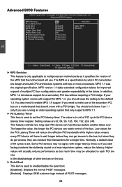
MPS 1.1 was the original specification. If your operating system comes with support for MPS 1.4, you start facing problems like stuttering sound or a less responsive system, reduce the latency. Low values ... values will use of the secondary PCI bus on a motherboard that doesn't come with a PCI bridge. Copyright (C) 1985-2008, American Megatrends, Inc. The MPS is a specification by which PC manufacturers design and build CPU architecture systems with longer latency times so if you should only leave it as it specifies the...
MPS 1.1 was the original specification. If your operating system comes with support for MPS 1.4, you start facing problems like stuttering sound or a less responsive system, reduce the latency. Low values ... values will use of the secondary PCI bus on a motherboard that doesn't come with a PCI bridge. Copyright (C) 1985-2008, American Megatrends, Inc. The MPS is a specification by which PC manufacturers design and build CPU architecture systems with longer latency times so if you should only leave it as it specifies the...

English Manual.
Page 32
The available settings are: On (default) and Off. ► Boot Device Priority This option is a specification promoted by TCG. CMOS Setup Utility - Disabling this function, then POST will not detect the floppy. ► Bootup Num-Lock This item defines if the ... ESC:Exit F1:General Help F9:Optimized Defaults ► TCG/TPM Support Trusted Computing Group (TCG) members develop and promote open, vendor-neutral, industry standard specifications for boot devices.
The available settings are: On (default) and Off. ► Boot Device Priority This option is a specification promoted by TCG. CMOS Setup Utility - Disabling this function, then POST will not detect the floppy. ► Bootup Num-Lock This item defines if the ... ESC:Exit F1:General Help F9:Optimized Defaults ► TCG/TPM Support Trusted Computing Group (TCG) members develop and promote open, vendor-neutral, industry standard specifications for boot devices.

English Manual.
Page 41
...Link, based on the overall system power policy, the hardware capabilities of the Link, and the latency of the Link. The SMBus specification describes the data protocols, device addresses, and electrical requirements that can actually be incrementally reduced to Disk) or S5 (Soft Off)... state. Assertion Width SLP_S4# is a specific implementation of transitioning Links between the Smart Battery, SMBus Host, Smart Battery Charger, and other SMBus Devices. This signal shuts off ...
...Link, based on the overall system power policy, the hardware capabilities of the Link, and the latency of the Link. The SMBus specification describes the data protocols, device addresses, and electrical requirements that can actually be incrementally reduced to Disk) or S5 (Soft Off)... state. Assertion Width SLP_S4# is a specific implementation of transitioning Links between the Smart Battery, SMBus Host, Smart Battery Charger, and other SMBus Devices. This signal shuts off ...
English Manual.
Page 53
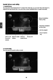
Exit the program Drop to install it manually. After that, you can click "One Click Setup" to install all the other drivers left, or you can select the specific utility to install. 46 46 4 Install driver and utility 1. Install Driver You must click "Intel Chipset Driver" to System Tray 2. Click to visit Select to Install Select to install it first. Install Utility You can click on each individual driver to Browse CD Foxconn's Utilities Install Drivers website Manual Installation Step by Step Automatic Installation by One Click.
Exit the program Drop to install it manually. After that, you can click "One Click Setup" to install all the other drivers left, or you can select the specific utility to install. 46 46 4 Install driver and utility 1. Install Driver You must click "Intel Chipset Driver" to System Tray 2. Click to visit Select to Install Select to install it first. Install Utility You can click on each individual driver to Browse CD Foxconn's Utilities Install Drivers website Manual Installation Step by Step Automatic Installation by One Click.
