English Manual.
Page 1
G41MX 2.0 Series Motherboard User's Manual
G41MX 2.0 Series Motherboard User's Manual
English Manual.
Page 2
... disposal service or the shop where you how to use of this symbol indicates that can help prevent potential negative consequences for G41MX 2.0 Series motherboard. More information: If you will help you to avoid problems. WARNING! Warning: indicating a potential risk of respective manufacturers listed.... By ensuring this product may not be changed or modified at any time, Foxconn does not obligate itself to important information that this product is the intellectual property of Foxconn, Inc. CAUTION Statement: This manual is disposed of correctly, you want more ...
... disposal service or the shop where you how to use of this symbol indicates that can help prevent potential negative consequences for G41MX 2.0 Series motherboard. More information: If you will help you to avoid problems. WARNING! Warning: indicating a potential risk of respective manufacturers listed.... By ensuring this product may not be changed or modified at any time, Foxconn does not obligate itself to important information that this product is the intellectual property of Foxconn, Inc. CAUTION Statement: This manual is disposed of correctly, you want more ...

English Manual.
Page 3
... information technology equipment ■ EN 61000-3-2/:2000 Electromagnetic compatibility (EMC) Part 3: Limits Section 2: Limits for harmonic current emissions (equipment input current declares that the product Motherboard G41MX 2.0/G41MX-K 2.0/G41MX-F 2.0 is in conformity with (reference to the specification under which conformity is declared in accordance with 89/336 EEC-EMC Directive) ■ EN 55022: 1998...
... information technology equipment ■ EN 61000-3-2/:2000 Electromagnetic compatibility (EMC) Part 3: Limits Section 2: Limits for harmonic current emissions (equipment input current declares that the product Motherboard G41MX 2.0/G41MX-K 2.0/G41MX-F 2.0 is in conformity with (reference to the specification under which conformity is declared in accordance with 89/336 EEC-EMC Directive) ■ EN 55022: 1998...
English Manual.
Page 4
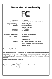
... 92835 714-738-8868 714-738-8838 Equipment Classification: Type of conformity Trade Name: Model Name: Responsible Party: Address: Telephone: Facsimile: FOXCONN G41MX 2.0/G41MX-K 2.0/ G41MX-F 2.0 PCE Industry Inc. 458 E. Declaration of Product: Manufacturer: Address: FCC Class B Subassembly Motherboard HON HAI PRECISION INDUSTRY COMPANY LTD 66 , CHUNG SHAN RD., TU-CHENG INDUSTRIAL DISTRICT, TAIPEI HSIEN, TAIWAN, R.O.C.
... 92835 714-738-8868 714-738-8838 Equipment Classification: Type of conformity Trade Name: Model Name: Responsible Party: Address: Telephone: Facsimile: FOXCONN G41MX 2.0/G41MX-K 2.0/ G41MX-F 2.0 PCE Industry Inc. 458 E. Declaration of Product: Manufacturer: Address: FCC Class B Subassembly Motherboard HON HAI PRECISION INDUSTRY COMPANY LTD 66 , CHUNG SHAN RD., TU-CHENG INDUSTRIAL DISTRICT, TAIPEI HSIEN, TAIWAN, R.O.C.

English Manual.
Page 5
... will quickly damage your electronic equipment. It is suggested to select high-quality, certified fans in order to avoid damage to the motherboard and CPU due to come in contact with the connectors on the overclocking capac- Never turn on the power, please make sure ...setting has been configured to the local standard. ■ To prevent damage to the motherboard, do not allow screws to high temperature. Incorrect connections might damage the motherboard. ■ When handling the motherboard, avoid touching any installation steps or have a problem related to unplug the AC power...
... will quickly damage your electronic equipment. It is suggested to select high-quality, certified fans in order to avoid damage to the motherboard and CPU due to come in contact with the connectors on the overclocking capac- Never turn on the power, please make sure ...setting has been configured to the local standard. ■ To prevent damage to the motherboard, do not allow screws to high temperature. Incorrect connections might damage the motherboard. ■ When handling the motherboard, avoid touching any installation steps or have a problem related to unplug the AC power...

English Manual.
Page 8
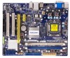
Foxconn products are engineered to unleash more power from your computer. This chapter includes the following information: ■ Product Specifications ■ Layout ■ Back Panel Connectors Thank you need for buying Foxconn G41MX 2.0 Series motherboard. With advanced overclocking capability and a range of connectivity features for today multi-media computing requirements, G41MX 2.0/G41MX-K 2.0/G41MX-F 2.0 enables you to maximize computing power, providing only what you for break-through performance.
Foxconn products are engineered to unleash more power from your computer. This chapter includes the following information: ■ Product Specifications ■ Layout ■ Back Panel Connectors Thank you need for buying Foxconn G41MX 2.0 Series motherboard. With advanced overclocking capability and a range of connectivity features for today multi-media computing requirements, G41MX 2.0/G41MX-K 2.0/G41MX-F 2.0 enables you to maximize computing power, providing only what you for break-through performance.

English Manual.
Page 11
... x1 Slot 5. CD_IN Connector 9. Clear CMOS Jumper 11. Front USB Connectors 13. SATA Connectors 16. IDE Connector 18. LGA 775 CPU Socket Note : The above motherboard layout is for reference only, please refer to the physical...
... x1 Slot 5. CD_IN Connector 9. Clear CMOS Jumper 11. Front USB Connectors 13. SATA Connectors 16. IDE Connector 18. LGA 775 CPU Socket Note : The above motherboard layout is for reference only, please refer to the physical...

English Manual.
Page 14
... ■ Install an Expansion Card ■ Install other Internal Connectors ■ Jumpers Please visit the following website for more supporting information about your motherboard. Please refer to the motherboard layout prior to any installation and read the contents in this chapter carefully. CPU Support List: http://www.foxconnsupport.com/cpusupportlist.aspx Memory...
... ■ Install an Expansion Card ■ Install other Internal Connectors ■ Jumpers Please visit the following website for more supporting information about your motherboard. Please refer to the motherboard layout prior to any installation and read the contents in this chapter carefully. CPU Support List: http://www.foxconnsupport.com/cpusupportlist.aspx Memory...

English Manual.
Page 15
... occur. ■ Set the CPU host frequency in accordance with the CPU specifications. If you begin to install the CPU : ■ Make sure that the motherboard supports the CPU. ■ Always turn on the CPU. Read the following guidelines before installing the CPU to prevent hardware damage. ■ Locate the pin... and CPU Cooler ! The CPU cannot be set the frequency beyond hardware specifications since it enabled Install the CPU Locate the alignment keys on the motherboard CPU socket and the notches on the computer if the CPU cooler is optimized for the peripherals.
... occur. ■ Set the CPU host frequency in accordance with the CPU specifications. If you begin to install the CPU : ■ Make sure that the motherboard supports the CPU. ■ Always turn on the CPU. Read the following guidelines before installing the CPU to prevent hardware damage. ■ Locate the pin... and CPU Cooler ! The CPU cannot be set the frequency beyond hardware specifications since it enabled Install the CPU Locate the alignment keys on the motherboard CPU socket and the notches on the computer if the CPU cooler is optimized for the peripherals.
English Manual.
Page 17
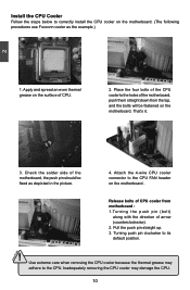
... the four bolts of the CPU cooler to the holes of the motherboard, push them straight down from motherboard : 1.Turning the push pin (bolt) along with the direction of... because the thermal grease may damage the CPU. 10 10 Check the solder side of the motherboard, the push pin should be fastened on the motherboard . 3 2 1 Release bolts of CPU cooler from the top, and the bolts will ... adhere to the CPU. Attach the 4-wire CPU cooler connector to the CPU FAN header on the motherboard. Turning push pin clockwise to its default position. ! Install the CPU Cooler Follow the steps below ...
... the four bolts of the CPU cooler to the holes of the motherboard, push them straight down from motherboard : 1.Turning the push pin (bolt) along with the direction of... because the thermal grease may damage the CPU. 10 10 Check the solder side of the motherboard, the push pin should be fastened on the motherboard . 3 2 1 Release bolts of CPU cooler from the top, and the bolts will ... adhere to the CPU. Attach the 4-wire CPU cooler connector to the CPU FAN header on the motherboard. Turning push pin clockwise to its default position. ! Install the CPU Cooler Follow the steps below ...

English Manual.
Page 18
... Dual Channel DS/SS DS/SS (DS : Double Side, SS : Single Side, - : No Memory) ! Dual Channel Memory Configuration This motherboard provides two DDR2 memory sockets and supports Dual Channel Technology. It is recommended that memory of the same capacity, brand, speed, and chips be ...used and please select dual channel first to install the memory : ■ Make sure that the motherboard supports the memory. CAUTION 11 11 CAUTION 2 2-2 Install the Memory ! Read the following guidelines before installing the memory to insert the memory...
... Dual Channel DS/SS DS/SS (DS : Double Side, SS : Single Side, - : No Memory) ! Dual Channel Memory Configuration This motherboard provides two DDR2 memory sockets and supports Dual Channel Technology. It is recommended that memory of the same capacity, brand, speed, and chips be ...used and please select dual channel first to install the memory : ■ Make sure that the motherboard supports the memory. CAUTION 11 11 CAUTION 2 2-2 Install the Memory ! Read the following guidelines before installing the memory to insert the memory...

English Manual.
Page 19
... of the socket will snap into the memory socket. Step 2: The clips at both ends of memory module, it has asymmetric pin counts on this motherboard. Before installing a memory module, make sure to turn off the computer and unplug the power cord from the power outlet to prevent damage to correctly...
... of the socket will snap into the memory socket. Step 2: The clips at both ends of memory module, it has asymmetric pin counts on this motherboard. Before installing a memory module, make sure to turn off the computer and unplug the power cord from the power outlet to prevent damage to correctly...
English Manual.
Page 20
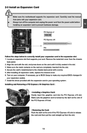
... in the expansion slot. 1. Carefully read the manual that supports your expansion card in the slot. 3. CAUTION 2 2-3 Install an Expansion Card ! ■ Make sure the motherboard supports the expansion card. Secure the card's metal bracket to make any required BIOS changes for your computer. Turn on the card until it is...
... in the expansion slot. 1. Carefully read the manual that supports your expansion card in the slot. 3. CAUTION 2 2-3 Install an Expansion Card ! ■ Make sure the motherboard supports the expansion card. Secure the card's metal bracket to make any required BIOS changes for your computer. Turn on the card until it is...
English Manual.
Page 21
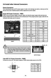
...and pins are using a 20-pin power supply, you using a 24-pin power supply. If you are properly aligned with the connector on the motherboard. Pin No. 24 20-Pin Power 4-pin ATX 12 V Power Connector : PWR2 Connect the 4-pin ATX 12V power supply to PWR2 and ...not to the CPU. 3 1 +12V GND 4 2 PWR2 Pin # 1 2 3 4 Definition GND GND +12V +12V 14 14 2 CAUTION 2-4 Install other Internal Connectors Power Connectors This motherboard uses an ATX power supply. Firmly plug the power supply cable into the connector and make sure all the devices have been installed properly before...
...and pins are using a 20-pin power supply, you using a 24-pin power supply. If you are properly aligned with the connector on the motherboard. Pin No. 24 20-Pin Power 4-pin ATX 12 V Power Connector : PWR2 Connect the 4-pin ATX 12V power supply to PWR2 and ...not to the CPU. 3 1 +12V GND 4 2 PWR2 Pin # 1 2 3 4 Definition GND GND +12V +12V 14 14 2 CAUTION 2-4 Install other Internal Connectors Power Connectors This motherboard uses an ATX power supply. Firmly plug the power supply cable into the connector and make sure all the devices have been installed properly before...
English Manual.
Page 22
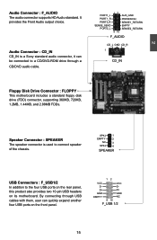
... In addition to a CD/DVD-ROM drive through USB cables with them, user can quickly expand another four USB ports on its motherboard. By connecting through a CD/DVD audio cable. Speaker Connector : SPEAKER The speaker connector is a Sony standard audio connector, it can... PORT1_R PORT2_R SENSE_SEND PORT2_L 12 9 10 AUD_GND PRESENCEJ SENSE1_RETURN EMPTY SENSE2_RETURN F_AUDIO CD_L GND CD_R 1 CD_IN Floppy Disk Drive Connector : FLOPPY This motherboard includes a standard floppy disk drive (FDD) connector, supporting 360KB, 720KB, 1.2MB, 1.44MB, and 2.88MB FDDs. D+ D+ GND GND EMPTY NC...
... In addition to a CD/DVD-ROM drive through USB cables with them, user can quickly expand another four USB ports on its motherboard. By connecting through a CD/DVD audio cable. Speaker Connector : SPEAKER The speaker connector is a Sony standard audio connector, it can... PORT1_R PORT2_R SENSE_SEND PORT2_L 12 9 10 AUD_GND PRESENCEJ SENSE1_RETURN EMPTY SENSE2_RETURN F_AUDIO CD_L GND CD_R 1 CD_IN Floppy Disk Drive Connector : FLOPPY This motherboard includes a standard floppy disk drive (FDD) connector, supporting 360KB, 720KB, 1.2MB, 1.44MB, and 2.88MB FDDs. D+ D+ GND GND EMPTY NC...
English Manual.
Page 23
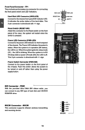
... the provided Ultra DMA IDE ribbon cable, you can connect to be turned on the front panel of the chassis. 2 Front Panel Connector : FP1 This motherboard includes one connector for connecting the front panel switch and LED Indicators. When the system gets into sleep mode (S1) , the LED is pressed. Power...
... the provided Ultra DMA IDE ribbon cable, you can connect to be turned on the front panel of the chassis. 2 Front Panel Connector : FP1 This motherboard includes one connector for connecting the front panel switch and LED Indicators. When the system gets into sleep mode (S1) , the LED is pressed. Power...
English Manual.
Page 24
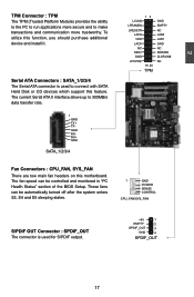
To utilize this motherboard. The fan speed can be controlled and monitored in "PC Health Status" section of the BIOS Setup. These fans can be automatically turned off after ...
To utilize this motherboard. The fan speed can be controlled and monitored in "PC Health Status" section of the BIOS Setup. These fans can be automatically turned off after ...
English Manual.
Page 25
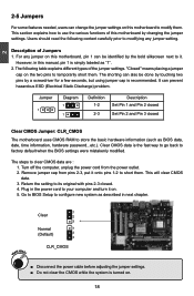
2 2-5 Jumpers For some features needed, users can change the jumper settings on this manual, pin 1 is simply labeled as "1". 2. Description of this motherboard, pin 1 can be done by touching two pins by a screwdriver for a few seconds, but using jumper cap is recommended. For any jumper setting. Jumper ...Plug in the power cord to your computer and turn it onto pins 1-2 to it. "Closed" means placing a jumper cap on this motherboard by the bold silkscreen next to short them. It can also be identified by changing the jumper settings. This section explains how to store the...
2 2-5 Jumpers For some features needed, users can change the jumper settings on this manual, pin 1 is simply labeled as "1". 2. Description of this motherboard, pin 1 can be done by touching two pins by a screwdriver for a few seconds, but using jumper cap is recommended. For any jumper setting. Jumper ...Plug in the power cord to your computer and turn it onto pins 1-2 to it. "Closed" means placing a jumper cap on this motherboard by the bold silkscreen next to short them. It can also be identified by changing the jumper settings. This section explains how to store the...
English Manual.
Page 31
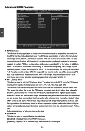
... use of the secondary PCI bus on the bus. ► Quiet Boot This item is only applicable to multiprocessor motherboards as it as 1.1 only if you start facing problems like stuttering sound or a less responsive system, reduce the latency. If your operating system comes ... also need to enable/disable the quiet boot. [Disabled] : Displays the normal POST messages. [Enabled] : Displays OEM customer logo instead of other devices on a motherboard that only supports MPS 1.1. ► PCI Latency Timer This item is set the PCI latency timer. This feature controls how long each PCI device to...
... use of the secondary PCI bus on the bus. ► Quiet Boot This item is only applicable to multiprocessor motherboards as it as 1.1 only if you start facing problems like stuttering sound or a less responsive system, reduce the latency. If your operating system comes ... also need to enable/disable the quiet boot. [Disabled] : Displays the normal POST messages. [Enabled] : Displays OEM customer logo instead of other devices on a motherboard that only supports MPS 1.1. ► PCI Latency Timer This item is set the PCI latency timer. This feature controls how long each PCI device to...

English Manual.
Page 35
...-2008, American Megatrends, Inc. The LED is selected, then pressing [Esc] has no function. This also prevents user without password trying to get into your motherboard to enter smart boot menu. Continue blinking On (1/2sec.), Off (1/2sec.) Stop Blinking Condition Always On Reboot & Memory OK Reboot & Display OK Enter Setup or...
...-2008, American Megatrends, Inc. The LED is selected, then pressing [Esc] has no function. This also prevents user without password trying to get into your motherboard to enter smart boot menu. Continue blinking On (1/2sec.), Off (1/2sec.) Stop Blinking Condition Always On Reboot & Memory OK Reboot & Display OK Enter Setup or...


