Product Manual
Page 2
... not apply to fuses, disposable batteries or to any other product, which is purchased through a Hart authorized sales outlet or Buyer has paid the applicable international price. Hart warrants that software will provide an estimate or repair costs and obtain authorization before commencing the work. Hart authorized resellers shall extend this warranty on new and unused products...
... not apply to fuses, disposable batteries or to any other product, which is purchased through a Hart authorized sales outlet or Buyer has paid the applicable international price. Hart warrants that software will provide an estimate or repair costs and obtain authorization before commencing the work. Hart authorized resellers shall extend this warranty on new and unused products...
Product Manual
Page 3
... Low Voltage Directive (Safety 9 1.6 Authorized Service Centers 9 2 Specifications and Environmental Conditions 13 2.1 Specifications 13 2.2 Environmental Conditions 15 3 Quick Start 17 3.1 Setup...17 3.2 Parts and Controls 18 3.2.1 Display Panel 19 3.2.2 Display...20 3.2.3 Power Panel 22 3.2.4 -P Option Panel (-P models only 24 3.3 Languages 26 3.3.1 Language Selection 26 3.3.2 Reset to English Language 27 4 Menu Structure 29 4.1 Temp Setup Menu 29 4.2 Prog Menu 30 4.2.1 Switch Test Parameters 31 4.2.2 Switch Test Description 31 4.3 System Menu 33 4.4 Input Setup (-P only...
... Low Voltage Directive (Safety 9 1.6 Authorized Service Centers 9 2 Specifications and Environmental Conditions 13 2.1 Specifications 13 2.2 Environmental Conditions 15 3 Quick Start 17 3.1 Setup...17 3.2 Parts and Controls 18 3.2.1 Display Panel 19 3.2.2 Display...20 3.2.3 Power Panel 22 3.2.4 -P Option Panel (-P models only 24 3.3 Languages 26 3.3.1 Language Selection 26 3.3.2 Reset to English Language 27 4 Menu Structure 29 4.1 Temp Setup Menu 29 4.2 Prog Menu 30 4.2.1 Switch Test Parameters 31 4.2.2 Switch Test Description 31 4.3 System Menu 33 4.4 Input Setup (-P only...

Product Manual
Page 6
...-on ferrite installation 9 Figure 2 914X Field Metrology Well 18 Figure 3 Display panel and keys 20 Figure 4 914X display 21 Figure 5 9142 power panel 23 Figure 6 9143 and 9144 power panel 23 Figure 7 -P option panel 24 Figure 8 Probe connector wiring 25 Figure 9 Jumper locations for Fluke products online at: www. .com 1.888.610.7664 Prog Menu 30 Figure 13 Auto and manual switch test operation example 32...
...-on ferrite installation 9 Figure 2 914X Field Metrology Well 18 Figure 3 Display panel and keys 20 Figure 4 914X display 21 Figure 5 9142 power panel 23 Figure 6 9143 and 9144 power panel 23 Figure 7 -P option panel 24 Figure 8 Probe connector wiring 25 Figure 9 Jumper locations for Fluke products online at: www. .com 1.888.610.7664 Prog Menu 30 Figure 13 Auto and manual switch test operation example 32...
Product Manual
Page 7
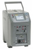
... for transmitter loop, comparison calibration, or a simple check of temperature 1 MyFlukeStore Shop for resistance, voltage, and mA measurement, 24V loop power, and on-board documentation. The LCD display continuously shows many useful operating parameters including the block temperature, the current set to show the information in mind and are displayed. The exclusive Voltage Compensation allows the technician to plug into...
... for transmitter loop, comparison calibration, or a simple check of temperature 1 MyFlukeStore Shop for resistance, voltage, and mA measurement, 24V loop power, and on-board documentation. The LCD display continuously shows many useful operating parameters including the block temperature, the current set to show the information in mind and are displayed. The exclusive Voltage Compensation allows the technician to plug into...
Product Manual
Page 9
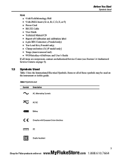
...; Power Cord ●● RS-232 Cable ●● User Guide ●● Technical Manual CD ●● Report of these symbols may be used Symbol Description AC (Alternating Current) AC-DC Battery Complies with European Union directives DC Double Insulated 3 MyFlukeStore Shop for Fluke products online at: www. .com 1.888.610.7664 Some or all of Calibration and calibration label ●● 6-pin...
...; Power Cord ●● RS-232 Cable ●● User Guide ●● Technical Manual CD ●● Report of these symbols may be used Symbol Description AC (Alternating Current) AC-DC Battery Complies with European Union directives DC Double Insulated 3 MyFlukeStore Shop for Fluke products online at: www. .com 1.888.610.7664 Some or all of Calibration and calibration label ●● 6-pin...

Product Manual
Page 12
... power cord of this instrument operate properly. Disconnect the test leads before turning it down with the inserts in accordance with a three-pronged grounding plug for operation at temperatures higher than upright. This instrument must be installed in place; 914X Field Metrology Wells Safety Information Never touch the probes to Table 2, Specifications . Select the proper function and range for Fluke products online...
... power cord of this instrument operate properly. Disconnect the test leads before turning it down with the inserts in accordance with a three-pronged grounding plug for operation at temperatures higher than upright. This instrument must be installed in place; 914X Field Metrology Wells Safety Information Never touch the probes to Table 2, Specifications . Select the proper function and range for Fluke products online...

Product Manual
Page 13
... lifetime can leak into electronics and damage the instrument. Always replace the power cord with an approved cord of this instrument at least 6 inches (15 cm) of the calibration constants from the factory set values. HIGH VOLTAGE is required. Before You Start Safety Information If supplied with user accessible fuses, always replace the fuse with one of these guidelines: DO NOT leave the inserts...
... lifetime can leak into electronics and damage the instrument. Always replace the power cord with an approved cord of this instrument at least 6 inches (15 cm) of the calibration constants from the factory set values. HIGH VOLTAGE is required. Before You Start Safety Information If supplied with user accessible fuses, always replace the fuse with one of these guidelines: DO NOT leave the inserts...

Product Manual
Page 14
... optimum durability and trouble free operation, it are sensitive instruments that ferrites clamped around probe cables for use . As noted in environments of Conformity for your instrument lists the specific standards to which the...user. 1.5 CE Comments 1.5.1 EMC Directive Hart Scientific's equipment has been tested to meet the European Electromagnetic Compatibility Directive (EMC Directive, 89/336/EEC). Always carry the instrument in an excessively wet, oily, dusty, or dirty environment. The convenient handle allows for Fluke products online at different rates. Wait until the power...
... optimum durability and trouble free operation, it are sensitive instruments that ferrites clamped around probe cables for use . As noted in environments of Conformity for your instrument lists the specific standards to which the...user. 1.5 CE Comments 1.5.1 EMC Directive Hart Scientific's equipment has been tested to meet the European Electromagnetic Compatibility Directive (EMC Directive, 89/336/EEC). Always carry the instrument in an excessively wet, oily, dusty, or dirty environment. The convenient handle allows for Fluke products online at different rates. Wait until the power...

Product Manual
Page 15
... 1 Clamp-on ferrite installation 1.5.3 Emission Testing The instrument fulfills the limit requirements for Fluke products online at: www. .com 1.888.610.7664 The ferrite can be easily snapped open and moved to a new probe when needed. Before You Start Authorized Service Centers we recommend that the clamp-on ferrites provided be used on the cables of probes attached to...
... 1 Clamp-on ferrite installation 1.5.3 Emission Testing The instrument fulfills the limit requirements for Fluke products online at: www. .com 1.888.610.7664 The ferrite can be easily snapped open and moved to a new probe when needed. Before You Start Authorized Service Centers we recommend that the clamp-on ferrites provided be used on the cables of probes attached to...
Product Manual
Page 20
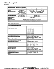
914X Field Metrology Wells Specifications Base Unit Specifications 9142 9143 9144 Weight Power Requirements System Fuse Ratings 4-20 mA Fuse (-P model only) Computer Interface Safety 8.16 kg (18 lbs) 100 V to 115 V (± 10 ...±0.0025 ohms 42 ohms to 400 ohms: ±60 ppm of reading ITS-90, CVD, IEC-751, Resistance 4-wire 6 Pin Din with Infocon Technology NI-120: ± 0.015 °C at 0 °C PT-100 (385): ± 0....385),(JIS),(3926), NI-120, Resistance 2-,3-,4-wire RTD w\ Jumpers only 4 terminal input 14 MyFlukeStore Shop for Fluke products online at: www. .com 1.888.610.7664
914X Field Metrology Wells Specifications Base Unit Specifications 9142 9143 9144 Weight Power Requirements System Fuse Ratings 4-20 mA Fuse (-P model only) Computer Interface Safety 8.16 kg (18 lbs) 100 V to 115 V (± 10 ...±0.0025 ohms 42 ohms to 400 ohms: ±60 ppm of reading ITS-90, CVD, IEC-751, Resistance 4-wire 6 Pin Din with Infocon Technology NI-120: ± 0.015 °C at 0 °C PT-100 (385): ± 0....385),(JIS),(3926), NI-120, Resistance 2-,3-,4-wire RTD w\ Jumpers only 4 terminal input 14 MyFlukeStore Shop for Fluke products online at: www. .com 1.888.610.7664
Product Manual
Page 23
...." If the instrument fails to set the desired set -point and enable the instrument. Plug the instrument power cord into the well. and use the arrow keys to operate, please check the power connection. Press "ENTER" to the calibrator by toggling the switch on a flat surface with the two small tong holes positioned upward. parameter is installed. DO NOT place under a cabinet or...
...." If the instrument fails to set the desired set -point and enable the instrument. Plug the instrument power cord into the well. and use the arrow keys to operate, please check the power connection. Press "ENTER" to the calibrator by toggling the switch on a flat surface with the two small tong holes positioned upward. parameter is installed. DO NOT place under a cabinet or...

Product Manual
Page 25
... to change depending on the display, change the display layout, and adjust the contrast of the display. Quick Start Parts and Controls Display (1) The display is selected. udlr Arrow Keys (2) The Arrow Keys allow you to access submenus and functions. SET PT. (4) The Set Pt. Menu Key (6) The Menu Key allows the user to F4). The contrast can use the soft keys to exit menus and cancel newly entered values. Switch Connector (9) The switch hold connector posts...
... to change depending on the display, change the display layout, and adjust the contrast of the display. Quick Start Parts and Controls Display (1) The display is selected. udlr Arrow Keys (2) The Arrow Keys allow you to access submenus and functions. SET PT. (4) The Set Pt. Menu Key (6) The Menu Key allows the user to F4). The contrast can use the soft keys to exit menus and cancel newly entered values. Switch Connector (9) The switch hold connector posts...

Product Manual
Page 26
... power, the indicator light flashes until the block cools to 60°C). Figure 3 Display panel and keys 3.2.2 Display The front panel display is shown in detail in the box at : www. .com 1.888.610.7664 The indicator light is shown in large digits in Figure 4 on the screen. 20 MyFlukeStore Shop for Fluke products online at the top of the screen. The indicator light...
... power, the indicator light flashes until the block cools to 60°C). Figure 3 Display panel and keys 3.2.2 Display The front panel display is shown in detail in the box at : www. .com 1.888.610.7664 The indicator light is shown in large digits in Figure 4 on the screen. 20 MyFlukeStore Shop for Fluke products online at the top of the screen. The indicator light...
Product Manual
Page 27
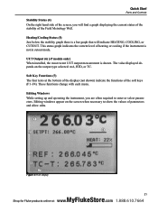
... a graph displaying the current status of the stability of the Field Metrology Well. Editing windows appear on the output type selected: mA, RTD, or TC. Quick Start Parts and Controls Stability Status (4) On the right hand side of the screen, you are often required to show the values of the soft keys (F1-F4). UUT Output (6) [-P models only] When installed, the most...
... a graph displaying the current status of the stability of the Field Metrology Well. Editing windows appear on the output type selected: mA, RTD, or TC. Quick Start Parts and Controls Stability Status (4) On the right hand side of the screen, you are often required to show the values of the soft keys (F1-F4). UUT Output (6) [-P models only] When installed, the most...

Product Manual
Page 28
... fuses are separate from the power connector (Figure 6 on the power panel to Specifications (see Figures 5 and Figure 6 on the power panel above the power entry module. Plug the cord into an AC mains supply appropriate for Fluke products online at the lower center of the power switch. On the 9143 and 9144, the serial connector is a 9-pin subminiature D type located on opposite page). Power Switch (2) For the 9142, the power switch...
... fuses are separate from the power connector (Figure 6 on the power panel to Specifications (see Figures 5 and Figure 6 on the power panel above the power entry module. Plug the cord into an AC mains supply appropriate for Fluke products online at the lower center of the power switch. On the 9143 and 9144, the serial connector is a 9-pin subminiature D type located on opposite page). Power Switch (2) For the 9142, the power switch...

Product Manual
Page 35
Units: Changes temperature units Up/Down Arrow Keys Up Key: Darker Down Key: Lighter F1 & F4 Keys (same time) F1 & F3 Keys (same time) 1 Beep - Valid key entry 2 Beep - Invalid key entry Code Update Mode Keys ENTER & EXIT Keys (hold during power up) Allows instrument software to be updated Figure 11 Main Menu - SETPOINT SETPOINT: Set point temperature ENTER F1 - Key - SELECT PRESET F1 - SAVE/DISABLE ºC / ºF Key - 4 Menu Structure Menu Structure Temp Setup Menu 4.1 Temp Setup Menu 9142/9143/9144...
Units: Changes temperature units Up/Down Arrow Keys Up Key: Darker Down Key: Lighter F1 & F4 Keys (same time) F1 & F3 Keys (same time) 1 Beep - Valid key entry 2 Beep - Invalid key entry Code Update Mode Keys ENTER & EXIT Keys (hold during power up) Allows instrument software to be updated Figure 11 Main Menu - SETPOINT SETPOINT: Set point temperature ENTER F1 - Key - SELECT PRESET F1 - SAVE/DISABLE ºC / ºF Key - 4 Menu Structure Menu Structure Temp Setup Menu 4.1 Temp Setup Menu 9142/9143/9144...

Product Manual
Page 36
... Prog Menu 4.2 Prog Menu 9142/9143/9144 MAIN MENU F1 TEMP SETUP F2 PROG MENU F3 SYSTEM MENU F4 INPUT SETUP (-P only) F1 RUN PROGram TEST STATUS: Changes status of times the Field Metrology Well repeats the manual test program F4 TEST RESULT (-P only) F1 VIEW TESTS DISPLAY TEST: Displays test results DATE: TIME: F2 PRINT TESTS PRINT TESTS: < NO, YES> Print all test data Figure 12 Main Menu - TEST...
... Prog Menu 4.2 Prog Menu 9142/9143/9144 MAIN MENU F1 TEMP SETUP F2 PROG MENU F3 SYSTEM MENU F4 INPUT SETUP (-P only) F1 RUN PROGram TEST STATUS: Changes status of times the Field Metrology Well repeats the manual test program F4 TEST RESULT (-P only) F1 VIEW TESTS DISPLAY TEST: Displays test results DATE: TIME: F2 PRINT TESTS PRINT TESTS: < NO, YES> Print all test data Figure 12 Main Menu - TEST...

Product Manual
Page 37
... how many times the instrument heats and cools allowing a thermal switch or batch of the Scan Rate during a cycle at : www. .com 1.888.610.7664 Under Switch Test, select Auto Test. Press Enter and the instrument will engage and start a cycle. Exit to be tested. 4.2.2 Switch Test Description CAUTION: The switch, switch wires, switch components and switch accessories can be tested for Auto or Manual operation.
... how many times the instrument heats and cools allowing a thermal switch or batch of the Scan Rate during a cycle at : www. .com 1.888.610.7664 Under Switch Test, select Auto Test. Press Enter and the instrument will engage and start a cycle. Exit to be tested. 4.2.2 Switch Test Description CAUTION: The switch, switch wires, switch components and switch accessories can be tested for Auto or Manual operation.

Product Manual
Page 41
... to see if the display shows cutout and the temperature is working properly. Ease of operation and simplicity of the instrument. This type of the appropriate gauge wire for Fluke products online at: www. .com 1.888.610.7664 If there are any questions, contact an Authorized Service Center for more information. ●● Before using any chance of jamming...
... to see if the display shows cutout and the temperature is working properly. Ease of operation and simplicity of the instrument. This type of the appropriate gauge wire for Fluke products online at: www. .com 1.888.610.7664 If there are any questions, contact an Authorized Service Center for more information. ●● Before using any chance of jamming...

Product Manual
Page 42
In the case that the calibration of the display value is required, a program of monitoring and recalibration must be implemented, just as with an adequate temperature reference and keep records as outlined in greater or lesser impact from handling or transportation will create changes requiring new calibration constants depending on the temperature range and normal operation of the instrument. For...
In the case that the calibration of the display value is required, a program of monitoring and recalibration must be implemented, just as with an adequate temperature reference and keep records as outlined in greater or lesser impact from handling or transportation will create changes requiring new calibration constants depending on the temperature range and normal operation of the instrument. For...


