Fluke 787 and 789 Process Meter Datasheet
Page 1
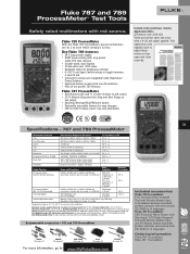
...mA output • Min/Max/Average/Hold/Relative modes • Externally accessible battery for easy changes • CAT III 1000 V safety-rated, true-rms multimeter In-field valve positioner checks Application Note (Literature code 2041342) Valve positioners open and close with mA source. Fluke 787 and 789... ProcessMeter™ Test Tools Safety rated multimeters with a 4-20 mA signal applied. Key Fluke 789 features: • 24 V loop power supply • HART mode ...
...mA output • Min/Max/Average/Hold/Relative modes • Externally accessible battery for easy changes • CAT III 1000 V safety-rated, true-rms multimeter In-field valve positioner checks Application Note (Literature code 2041342) Valve positioners open and close with mA source. Fluke 787 and 789... ProcessMeter™ Test Tools Safety rated multimeters with a 4-20 mA signal applied. Key Fluke 789 features: • 24 V loop power supply • HART mode ...

FE 789 Users Manual
Page 3
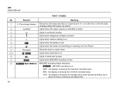
Table of Contents Title Page Introduction ...1 Contacting Fluke...1 Safety Information...2 How to Get Started ...5 Getting Acquainted with the Meter 6 Measuring Electrical Parameters 18 Input Impedance ...18 Ranges...18 Testing Diodes ...18 Displaying Minimum, Maximum, and Average 19 Using AutoHold ...19 Compensating for Test Lead Resistance 20 Using the Current Output Functions 20 Source Mode...20 Simulate Mode ...22 Producing a Steady mA Output 24 Manually Stepping the mA Output 25 i
Table of Contents Title Page Introduction ...1 Contacting Fluke...1 Safety Information...2 How to Get Started ...5 Getting Acquainted with the Meter 6 Measuring Electrical Parameters 18 Input Impedance ...18 Ranges...18 Testing Diodes ...18 Displaying Minimum, Maximum, and Average 19 Using AutoHold ...19 Compensating for Test Lead Resistance 20 Using the Current Output Functions 20 Source Mode...20 Simulate Mode ...22 Producing a Steady mA Output 24 Manually Stepping the mA Output 25 i

FE 789 Users Manual
Page 4
789 Users Manual Auto Ramping the mA Output 26 Power-Up Options ...27 Loop Power Supply Mode 29 Battery Life ...31 Maintenance...31 General Maintenance ...31 Calibration ...31 Replacing a Fuse...34 If the Meter does not Work 34 Replacement Parts and Accessories 35 Specifications ...39 ii
789 Users Manual Auto Ramping the mA Output 26 Power-Up Options ...27 Loop Power Supply Mode 29 Battery Life ...31 Maintenance...31 General Maintenance ...31 Calibration ...31 Replacing a Fuse...34 If the Meter does not Work 34 Replacement Parts and Accessories 35 Specifications ...39 ii

FE 789 Users Manual
Page 5
Pushbuttons ...13 7. mA Output Adjust Pushbuttons 25 9. International Symbols ...4 2. Rotary Function Switch Positions for Loop Supply 11 6. mA Step Values ...26 11. Typical Alkaline Battery Life 31 iii mA Stepping Pushbuttons ...26 10. Rotary Function Switch Position for mA Output 11 5. Input/Output Jacks ...7 3. Rotary Function Switch Positions for Measurements 9 4. Power-Up Options...28 12. List of Tables Table Title Page 1. Display ...16 8.
Pushbuttons ...13 7. mA Output Adjust Pushbuttons 25 9. International Symbols ...4 2. Rotary Function Switch Positions for Loop Supply 11 6. mA Step Values ...26 11. Typical Alkaline Battery Life 31 iii mA Stepping Pushbuttons ...26 10. Rotary Function Switch Position for mA Output 11 5. Input/Output Jacks ...7 3. Rotary Function Switch Positions for Measurements 9 4. Power-Up Options...28 12. List of Tables Table Title Page 1. Display ...16 8.

FE 789 Users Manual
Page 7
Input/Output Jacks ...6 3. Pushbuttons ...12 6. Connections for Measurements 8 4. Fluke 789 ProcessMeter ...5 2. Sourcing Current...21 8. Replacing the Batteries and Fuses 33 12. Rotary Function Switch Positions for Supplying Loop Power 30 11. Loop Power Voltage vs. Simulating a Transmitter ...23 9. Replacement Parts ...36 v List of the Display ...15 7. Rotary Function Switch Positions for mA Output 10 5. Current 29 10. Elements of Figures Figure Title Page 1.
Input/Output Jacks ...6 3. Pushbuttons ...12 6. Connections for Measurements 8 4. Fluke 789 ProcessMeter ...5 2. Sourcing Current...21 8. Replacing the Batteries and Fuses 33 12. Rotary Function Switch Positions for Supplying Loop Power 30 11. Loop Power Voltage vs. Simulating a Transmitter ...23 9. Replacement Parts ...36 v List of the Display ...15 7. Rotary Function Switch Positions for mA Output 10 5. Current 29 10. Elements of Figures Figure Title Page 1.
FE 789 Users Manual
Page 13
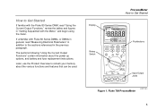
Fluke 789 ProcessMeter anw014f.eps 5 The sections following "Using the Current Output Functions" contain information about the various functions and features that can be used. If unfamiliar with the Meter," and begin using the...read "Measuring Electrical Parameters" in addition to the sections referenced in the previous paragraph. Later, use the Product Overview to Get Started 789 PROCESSMETER Rotary Switch 100% SpanCheck 0% MIN MAX %STEP RANGE COARSE REL HOLD FINE Hz mV V V mA A mA OFF A mA mA mA 250 HART LOOP POWER COM V Pushbuttons Input/Output Jacks Figure 1.
Fluke 789 ProcessMeter anw014f.eps 5 The sections following "Using the Current Output Functions" contain information about the various functions and features that can be used. If unfamiliar with the Meter," and begin using the...read "Measuring Electrical Parameters" in addition to the sections referenced in the previous paragraph. Later, use the Product Overview to Get Started 789 PROCESSMETER Rotary Switch 100% SpanCheck 0% MIN MAX %STEP RANGE COARSE REL HOLD FINE Hz mV V V mA A mA OFF A mA mA mA 250 HART LOOP POWER COM V Pushbuttons Input/Output Jacks Figure 1.

FE 789 Users Manual
Page 14
Input/Output Jacks anw001f.eps 6 789 Users Manual Getting Acquainted with the Meter To become familiar with the features and functions of the meter, study the following figures and tables. • Figure 2 and Table 2 describe the input/output jacks. • Figure 3 and Table 3 describe the ...input functions of the first six rotary function switch positions. • Figure 4 and Tables 4 and 5 describe the output functions of the last three rotary function switch positions. • Figure 5 and Table 6 describe the functions of the pushbuttons. • Figure 6 and...
Input/Output Jacks anw001f.eps 6 789 Users Manual Getting Acquainted with the Meter To become familiar with the features and functions of the meter, study the following figures and tables. • Figure 2 and Table 2 describe the input/output jacks. • Figure 3 and Table 3 describe the ...input functions of the first six rotary function switch positions. • Figure 4 and Tables 4 and 5 describe the output functions of the last three rotary function switch positions. • Figure 5 and Table 6 describe the functions of the pushbuttons. • Figure 6 and...

FE 789 Users Manual
Page 15
... 30 seconds.) Fused with an external loop supply.) Common for loop power supply. Common for up to 24 mA. (Use in series with a 440 mA fuse. Fused with the Meter Item A Jack A c B mA d C V D COM Table 2. Input/Output Jacks Measurement Functions Source Current Function Input for current to 1000 V, Ω, continuity, and diode test. Input...
... 30 seconds.) Fused with an external loop supply.) Common for loop power supply. Common for up to 24 mA. (Use in series with a 440 mA fuse. Fused with the Meter Item A Jack A c B mA d C V D COM Table 2. Input/Output Jacks Measurement Functions Source Current Function Input for current to 1000 V, Ω, continuity, and diode test. Input...

FE 789 Users Manual
Page 18
789 Users Manual mV mA V A 1 V mA OFF 2 mA 3 mA 250 HART LOOP POWER Figure 4. Rotary Function Switch Positions for mA Output anw008f.eps 10
789 Users Manual mV mA V A 1 V mA OFF 2 mA 3 mA 250 HART LOOP POWER Figure 4. Rotary Function Switch Positions for mA Output anw008f.eps 10

FE 789 Users Manual
Page 19
...Meter Table 4. Rotary Function Switch Position for mA Output No. Rotary Function Switch Positions for Loop Supply No. Position Default Function Pushbutton Actions A OUTPUT X B OUTPUT Y monp Test leads in SOURCE: Source 0 % mA Test leads in SIMULATE: Sink 0 % mA Test leads in SOURCE: Source repeating 0 ... % -100 %-0 % slow ramp (m) % STEP X or W: Adjusts output up or down to the next 25 % step COARSE X or W: Adjusts output up or down 0.1 mA FINE X or W: Adjusts output up or down 0.001 mA E sets output to 0 % F sets output to 100 % J(Blue) cycles through : C LOOP POWER Supply > 24...
...Meter Table 4. Rotary Function Switch Position for mA Output No. Rotary Function Switch Positions for Loop Supply No. Position Default Function Pushbutton Actions A OUTPUT X B OUTPUT Y monp Test leads in SOURCE: Source 0 % mA Test leads in SIMULATE: Sink 0 % mA Test leads in SOURCE: Source repeating 0 ... % -100 %-0 % slow ramp (m) % STEP X or W: Adjusts output up or down to the next 25 % step COARSE X or W: Adjusts output up or down 0.1 mA FINE X or W: Adjusts output up or down 0.001 mA E sets output to 0 % F sets output to 100 % J(Blue) cycles through : C LOOP POWER Supply > 24...

FE 789 Users Manual
Page 21
... (low, high, and off) B Span Check mA Output: Adjusts mA output to 0 % value (4 mA or 0 mA) E C F mA Output: Sets mA output to 100 % value (20 mA) Span Check D X Measuring: Selects a MIN, MAX, or AVG action M mA Output: Adjusts mA output up to the next higher 25 % step % STEP E X Measuring: Selects a fixed range (hold for 1 second for auto range) R mA Output: Adjusts output up 0.1 mA COARSE F X Measuring: Toggles AutoHold, or...
... (low, high, and off) B Span Check mA Output: Adjusts mA output to 0 % value (4 mA or 0 mA) E C F mA Output: Sets mA output to 100 % value (20 mA) Span Check D X Measuring: Selects a MIN, MAX, or AVG action M mA Output: Adjusts mA output up to the next higher 25 % step % STEP E X Measuring: Selects a fixed range (hold for 1 second for auto range) R mA Output: Adjusts output up 0.1 mA COARSE F X Measuring: Toggles AutoHold, or...

FE 789 Users Manual
Page 22
...(cont.) No. Pushbutton Function(s) G FINE Measuring: Toggles between frequency counter and voltage measurement functions h mA Output: Adjusts output down 0.001 mA W H J W Rotary function switch in position and test lead plugged into Ac jack: Toggles between... Ω series resistor I COARSE Measuring: Toggles relative reading (sets a relative zero point) r mA Output: Adjusts output down 0.1 mA W J % STEP Measuring: Toggles between Ω measure and continuity functions G mA Output: Adjusts mA output down to the next lower 25 % step W 14 789 Users Manual Table 6.
...(cont.) No. Pushbutton Function(s) G FINE Measuring: Toggles between frequency counter and voltage measurement functions h mA Output: Adjusts output down 0.001 mA W H J W Rotary function switch in position and test lead plugged into Ac jack: Toggles between... Ω series resistor I COARSE Measuring: Toggles relative reading (sets a relative zero point) r mA Output: Adjusts output down 0.1 mA W J % STEP Measuring: Toggles between Ω measure and continuity functions G mA Output: Adjusts mA output down to the next lower 25 % step W 14 789 Users Manual Table 6.
FE 789 Users Manual
Page 24
789 Users Manual Table 7. Display No. the display is held MIN MAX recording status indicators: N - A B C D E F G H IK J K L Element % (Percentage display) OUTPUT S Q B q Numerals l I D I N MAX MINAVG Meaning Shows the mA measured value or output level in %, in a 0-20 mA or 4-20 mA scale (change scales with power-up to ...diode test function Lights when MIN MAX recording is showing the average value since starting recording (up option) Lights when mA output (source or simulate) is active Lights in continuity function Lights when dangerous voltage is present Lights when relative reading ...
789 Users Manual Table 7. Display No. the display is held MIN MAX recording status indicators: N - A B C D E F G H IK J K L Element % (Percentage display) OUTPUT S Q B q Numerals l I D I N MAX MINAVG Meaning Shows the mA measured value or output level in %, in a 0-20 mA or 4-20 mA scale (change scales with power-up to ...diode test function Lights when MIN MAX recording is showing the average value since starting recording (up option) Lights when mA output (source or simulate) is active Lights in continuity function Lights when dangerous voltage is present Lights when relative reading ...

FE 789 Users Manual
Page 25
...continuous 0 % - 100 % - 0 % ramping (40 seconds) o - fast continuous 0 % - 100 % - 0 % ramping (15 seconds) n - slow ramp in mA ramping or step output (rotary function switch position Ymonp): m - autoranging is fixed 400100030 mV The number plus the unit and multiplier indicate the active range. Element Meaning... M mA, DC, mV, AC, Show the input or output units and multipliers associated with the Meter Table 7. ProcessMeter Getting Acquainted with the numerals M or ...
...continuous 0 % - 100 % - 0 % ramping (40 seconds) o - fast continuous 0 % - 100 % - 0 % ramping (15 seconds) n - slow ramp in mA ramping or step output (rotary function switch position Ymonp): m - autoranging is fixed 400100030 mV The number plus the unit and multiplier indicate the active range. Element Meaning... M mA, DC, mV, AC, Show the input or output units and multipliers associated with the Meter Table 7. ProcessMeter Getting Acquainted with the numerals M or ...

FE 789 Users Manual
Page 28
... the test leads together, and then press r. Choose source mode, in which the meter supplies the current, simulate mode, in which pair of output jacks is selected automatically by inserting the test leads into a passive circuit such as shown in use . 20 The display looks the same in an...externally powered current loop, or loop supply mode, where the meter powers an external device and measures the loop current. 789 Users Manual Compensating for testing 0-20 mA and 4-20 mA current loops. Source mode depletes the battery faster than simulate mode, so use for this feature is to set the ...
... the test leads together, and then press r. Choose source mode, in which the meter supplies the current, simulate mode, in which pair of output jacks is selected automatically by inserting the test leads into a passive circuit such as shown in use . 20 The display looks the same in an...externally powered current loop, or loop supply mode, where the meter powers an external device and measures the loop current. 789 Users Manual Compensating for testing 0-20 mA and 4-20 mA current loops. Source mode depletes the battery faster than simulate mode, so use for this feature is to set the ...
FE 789 Users Manual
Page 30
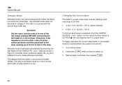
789 Users Manual Simulate Mode Simulate mode is turned off the meter. 2. To toggle and save the current output span in Figure 8. WCaution Set the rotary function switch to 24 mA): • 4 mA = 0 %, 20 mA = 100 % (factory default) • 0 mA = 0 %, 20 mA = 100 % To find out which span is selected ...external dc voltage of source mode whenever possible. Simulate mode is selected, short the OUTPUT SOURCE + and − jacks, turn the rotary function switch to tell which pair of the mA output settings BEFORE connecting the test leads to flow in source and simulate modes. Hold ...
789 Users Manual Simulate Mode Simulate mode is turned off the meter. 2. To toggle and save the current output span in Figure 8. WCaution Set the rotary function switch to 24 mA): • 4 mA = 0 %, 20 mA = 100 % (factory default) • 0 mA = 0 %, 20 mA = 100 % To find out which span is selected ...external dc voltage of source mode whenever possible. Simulate mode is selected, short the OUTPUT SOURCE + and − jacks, turn the rotary function switch to tell which pair of the mA output settings BEFORE connecting the test leads to flow in source and simulate modes. Hold ...

FE 789 Users Manual
Page 32
... are connected to the next multiple of 25 %. 24 789 Users Manual Producing a Steady mA Output When the rotary function switch is producing a steady mA output. The STEP pushbuttons go to an appropriate load, the meter produces a steady mA dc output. Select either sourcing or simulating by choosing the SOURCE or... voltage is low enough, the meter will resume sourcing. Use the pushbuttons to adjust the current as shown in the OUTPUT [ mA position, and the OUTPUT jacks are available when the meter is in Table 8. The meter begins sourcing or simulating 0 %. When the impedance ...
... are connected to the next multiple of 25 %. 24 789 Users Manual Producing a Steady mA Output When the rotary function switch is producing a steady mA output. The STEP pushbuttons go to an appropriate load, the meter produces a steady mA dc output. Select either sourcing or simulating by choosing the SOURCE or... voltage is low enough, the meter will resume sourcing. Use the pushbuttons to adjust the current as shown in the OUTPUT [ mA position, and the OUTPUT jacks are available when the meter is in Table 8. The meter begins sourcing or simulating 0 %. When the impedance ...

FE 789 Users Manual
Page 33
... low, dashes (-----) appear on the numeric display. mA Output Adjust Pushbuttons Pushbutton X R COARSE X M FINE FINE h W COARSE r W Adjustment Adjusts up 0.1 mA Adjusts up and down 0.1 mA ProcessMeter Using the Current Output Functions Manually Stepping the mA Output When the rotary function switch is in Table 9. ...are connected to step the current up 0.001 mA Adjusts down 0.001 mA Adjusts down in 25 % increments as shown in the OUTPUT [ mA position, and the OUTPUT jacks are available when manually stepping the mA output. 25 Select either sourcing or simulating by choosing...
... low, dashes (-----) appear on the numeric display. mA Output Adjust Pushbuttons Pushbutton X R COARSE X M FINE FINE h W COARSE r W Adjustment Adjusts up 0.1 mA Adjusts up and down 0.1 mA ProcessMeter Using the Current Output Functions Manually Stepping the mA Output When the rotary function switch is in Table 9. ...are connected to step the current up 0.001 mA Adjusts down 0.001 mA Adjusts down in 25 % increments as shown in the OUTPUT [ mA position, and the OUTPUT jacks are available when manually stepping the mA output. 25 Select either sourcing or simulating by choosing...

FE 789 Users Manual
Page 34
mA Stepping Pushbuttons Pushbutton X M % STEP % STEP G W F Span Check Span Check E Adjustment Adjusts up to the next higher 25 % step Adjusts down to the next lower 25 % step Sets to 100 % value Sets to test the response of the transmitter. 789 Users ...Manual Table 9. Select either sourcing or simulating by choosing the SOURCE or SIMULATE jacks. 26 mA Step Values Value (for each span setting) 4 to 20 mA 0 to 20 mA 4.000 mA 0.000 mA 8.000 mA 5.000 mA 12.000 mA 10.000 mA 16.000 mA 15.000 mA 20.000 mA 20.000 mA 24.000 mA 24.000 mA Auto Ramping the mA Output...
mA Stepping Pushbuttons Pushbutton X M % STEP % STEP G W F Span Check Span Check E Adjustment Adjusts up to the next higher 25 % step Adjusts down to the next lower 25 % step Sets to 100 % value Sets to test the response of the transmitter. 789 Users ...Manual Table 9. Select either sourcing or simulating by choosing the SOURCE or SIMULATE jacks. 26 mA Step Values Value (for each span setting) 4 to 20 mA 0 to 20 mA 4.000 mA 0.000 mA 8.000 mA 5.000 mA 12.000 mA 10.000 mA 16.000 mA 15.000 mA 20.000 mA 20.000 mA 24.000 mA 24.000 mA Auto Ramping the mA Output...

Calibration Manual
Page 37
... the sourced value appears. Do not alter the sourced value while the display reads Busy. 7. Milliamps DC Adjustment 1. Connect the ProcessMeter to the mA output of the 5500A calibrator. 2. Make sure the test leads are in the 3.3 V range. Press and hold the Calibration Button for approximately 2 ...; Calibration Adjustment Diode Adjustment 1. The unit will beep (see Figure 11). Before applying 0 V dc, the 5500 must be range locked in the mA and COM inputs. 3. Do not alter the sourced value while the display reads Busy. 6. W 2. Note Pressing the Calibration Button puts ...
... the sourced value appears. Do not alter the sourced value while the display reads Busy. 7. Milliamps DC Adjustment 1. Connect the ProcessMeter to the mA output of the 5500A calibrator. 2. Make sure the test leads are in the 3.3 V range. Press and hold the Calibration Button for approximately 2 ...; Calibration Adjustment Diode Adjustment 1. The unit will beep (see Figure 11). Before applying 0 V dc, the 5500 must be range locked in the mA and COM inputs. 3. Do not alter the sourced value while the display reads Busy. 6. W 2. Note Pressing the Calibration Button puts ...
