
Fluke 787 and 789 Process Meter Datasheet
Page 1
.../ISA S82.01-1994 and CAN/CSA C22.2 No. 1010.1-92 Over-voltage Category III Size (HxWxL)/weight (787 with mA source. Ordering information Fluke-789 ProcessMeter Fluke-787 ProcessMeter For more while carrying a lot less. This application note explains how to adjust these valves so they open and close with four AA... or 4.000 to 20.000 mA (selectable at power-up) Over-range to 24.000 mA 789: 24 V compliance or, 1,200 Ohms, @ 20 mA 787: 12 V compliance or, 500 Ohms, @ 20 mA .05 % .05 % DC current simulate (Ext. 24 Volt loop supply) 0.000 to 20.000 mA or 4.000 to 20.000...
.../ISA S82.01-1994 and CAN/CSA C22.2 No. 1010.1-92 Over-voltage Category III Size (HxWxL)/weight (787 with mA source. Ordering information Fluke-789 ProcessMeter Fluke-787 ProcessMeter For more while carrying a lot less. This application note explains how to adjust these valves so they open and close with four AA... or 4.000 to 20.000 mA (selectable at power-up) Over-range to 24.000 mA 789: 24 V compliance or, 1,200 Ohms, @ 20 mA 787: 12 V compliance or, 500 Ohms, @ 20 mA .05 % .05 % DC current simulate (Ext. 24 Volt loop supply) 0.000 to 20.000 mA or 4.000 to 20.000...

FE 789 Users Manual
Page 3
Table of Contents Title Page Introduction ...1 Contacting Fluke...1 Safety Information...2 How to Get Started ...5 Getting Acquainted with the Meter 6 Measuring Electrical Parameters 18 Input Impedance ...18 Ranges...18 Testing Diodes ...18 Displaying Minimum, Maximum, and Average 19 Using AutoHold ...19 Compensating for Test Lead Resistance 20 Using the Current Output Functions 20 Source Mode...20 Simulate Mode ...22 Producing a Steady mA Output 24 Manually Stepping the mA Output 25 i
Table of Contents Title Page Introduction ...1 Contacting Fluke...1 Safety Information...2 How to Get Started ...5 Getting Acquainted with the Meter 6 Measuring Electrical Parameters 18 Input Impedance ...18 Ranges...18 Testing Diodes ...18 Displaying Minimum, Maximum, and Average 19 Using AutoHold ...19 Compensating for Test Lead Resistance 20 Using the Current Output Functions 20 Source Mode...20 Simulate Mode ...22 Producing a Steady mA Output 24 Manually Stepping the mA Output 25 i

FE 789 Users Manual
Page 7
Pushbuttons ...12 6. Elements of Figures Figure Title Page 1. Connections for Measurements 8 4. Loop Power Voltage vs. Sourcing Current...21 8. Replacing the Batteries and Fuses 33 12. Current 29 10. Rotary Function Switch Positions for Supplying Loop Power 30 11. Simulating a Transmitter ...23 9. Fluke 789 ProcessMeter ...5 2. Input/Output Jacks ...6 3. Rotary Function Switch Positions for mA Output 10 5. List of the Display ...15 7. Replacement Parts ...36 v
Pushbuttons ...12 6. Elements of Figures Figure Title Page 1. Connections for Measurements 8 4. Loop Power Voltage vs. Sourcing Current...21 8. Replacing the Batteries and Fuses 33 12. Current 29 10. Rotary Function Switch Positions for Supplying Loop Power 30 11. Simulating a Transmitter ...23 9. Fluke 789 ProcessMeter ...5 2. Input/Output Jacks ...6 3. Rotary Function Switch Positions for mA Output 10 5. List of the Display ...15 7. Replacement Parts ...36 v

FE 789 Users Manual
Page 15
...with an external loop supply.) Common for current to 1000 V, Ω, continuity, and diode test. Fused with the Meter Item A Jack A c B mA d C V D COM Table 2. Simulate Transmitter Function Output for transmitter simulation to 24 mA. (Use in series with a 440 mA fuse. Output for all measurements. Input for transmitter... simulation to 24 mA. Input for dc current output to 30 seconds.) Fused with an external loop supply.) 7 Common for voltage to 30 mA. ...
...with an external loop supply.) Common for current to 1000 V, Ω, continuity, and diode test. Fused with the Meter Item A Jack A c B mA d C V D COM Table 2. Simulate Transmitter Function Output for transmitter simulation to 24 mA. (Use in series with a 440 mA fuse. Output for all measurements. Input for transmitter... simulation to 24 mA. Input for dc current output to 30 seconds.) Fused with an external loop supply.) 7 Common for voltage to 30 mA. ...

FE 789 Users Manual
Page 19
... No. Position Default Function Pushbutton Actions A OUTPUT X B OUTPUT Y monp Test leads in SOURCE: Source 0 % mA Test leads in SIMULATE: Sink 0 % mA Test leads in SOURCE: Source repeating 0 % -100 %-0 % slow ramp (m) Test leads in SIMULATE: Sink repeating 0 % -100 %-0 % slow ramp (m) % STEP X or W: Adjusts output up or down to the next 25 % step COARSE...
... No. Position Default Function Pushbutton Actions A OUTPUT X B OUTPUT Y monp Test leads in SOURCE: Source 0 % mA Test leads in SIMULATE: Sink 0 % mA Test leads in SOURCE: Source repeating 0 % -100 %-0 % slow ramp (m) Test leads in SIMULATE: Sink repeating 0 % -100 %-0 % slow ramp (m) % STEP X or W: Adjusts output up or down to the next 25 % step COARSE...
FE 789 Users Manual
Page 24
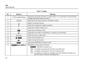
the display is showing the average value since starting recording (up option) Lights when mA output (source or simulate) is active Lights in continuity function Lights when dangerous voltage is present Lights when relative reading is on Lights when the battery is low Lights ... 4-20 mA scale (change scales with power-up to about 40 hours continuous recording time) 16 the display is showing the minimum-recorded value AVG - 789 Users Manual Table 7. the display is held MIN MAX recording status indicators: N -
the display is showing the average value since starting recording (up option) Lights when mA output (source or simulate) is active Lights in continuity function Lights when dangerous voltage is present Lights when relative reading is on Lights when the battery is low Lights ... 4-20 mA scale (change scales with power-up to about 40 hours continuous recording time) 16 the display is showing the minimum-recorded value AVG - 789 Users Manual Table 7. the display is held MIN MAX recording status indicators: N -

FE 789 Users Manual
Page 28
...as a current loop with no loop supply. Source mode depletes the battery faster than simulate mode, so use for this feature is necessary to set the present measurement as shown in Figure 7. 789 Users Manual Compensating for Test Lead Resistance Use the relative reading feature (Q on the ...to supply current into the SOURCE + and − jacks as a relative zero. Choose source mode, in which the meter supplies the current, simulate mode, in use . 20 Using the Current Output Functions The meter provides steady, stepped, and ramped current output for test lead resistance when measuring...
...as a current loop with no loop supply. Source mode depletes the battery faster than simulate mode, so use for this feature is necessary to set the present measurement as shown in Figure 7. 789 Users Manual Compensating for Test Lead Resistance Use the relative reading feature (Q on the ...to supply current into the SOURCE + and − jacks as a relative zero. Choose source mode, in which the meter supplies the current, simulate mode, in use . 20 Using the Current Output Functions The meter provides steady, stepped, and ramped current output for test lead resistance when measuring...
FE 789 Users Manual
Page 30
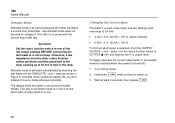
789 Users Manual Simulate Mode Simulate mode is selected, short the OUTPUT SOURCE + and − jacks, turn the rotary function switch to a current loop. Simulate mode is in series with overrange to 24 mA): • 4 mA = 0 %, 20 mA = 100 % (factory default) • 0 mA = 0 %, 20 mA = 100 % .... To toggle and save the current output span in use is to see which span is so named because the meter simulates a current loop transmitter. Use simulate mode when an external dc voltage of source mode whenever possible. Otherwise, a low impedance from the other rotary function switch positions...
789 Users Manual Simulate Mode Simulate mode is selected, short the OUTPUT SOURCE + and − jacks, turn the rotary function switch to a current loop. Simulate mode is in series with overrange to 24 mA): • 4 mA = 0 %, 20 mA = 100 % (factory default) • 0 mA = 0 %, 20 mA = 100 % .... To toggle and save the current output span in use is to see which span is so named because the meter simulates a current loop transmitter. Use simulate mode when an external dc voltage of source mode whenever possible. Otherwise, a low impedance from the other rotary function switch positions...

FE 789 Users Manual
Page 31
Simulating a Transmitter anw011f.eps 23 dc V Power Supply COM +24V 789 PROCESSMETER 100% SpanCheck 0% MIN MAX %STEP RANGE COARSE REL HOLD FINE Hz mV V V mA A mA OFF A mA mA mA 250 HART LOOP POWER COM V ProcessMeter Using the Current Output Functions 40 20 60 80 0 100 Figure 8.
Simulating a Transmitter anw011f.eps 23 dc V Power Supply COM +24V 789 PROCESSMETER 100% SpanCheck 0% MIN MAX %STEP RANGE COARSE REL HOLD FINE Hz mV V V mA A mA OFF A mA mA mA 250 HART LOOP POWER COM V ProcessMeter Using the Current Output Functions 40 20 60 80 0 100 Figure 8.

FE 789 Users Manual
Page 32
Select either sourcing or simulating by choosing the SOURCE or SIMULATE output jacks. If the meter cannot deliver the programmed current because the load resistance is too high or the loop supply voltage is low enough, ... the pushbuttons to the next multiple of 25 %. 24 When the impedance between the SOURCE jacks is too low, dashes (-----) appear on the numeric display. 789 Users Manual Producing a Steady mA Output When the rotary function switch is in Table 8. The meter begins sourcing or...
Select either sourcing or simulating by choosing the SOURCE or SIMULATE output jacks. If the meter cannot deliver the programmed current because the load resistance is too high or the loop supply voltage is low enough, ... the pushbuttons to the next multiple of 25 %. 24 When the impedance between the SOURCE jacks is too low, dashes (-----) appear on the numeric display. 789 Users Manual Producing a Steady mA Output When the rotary function switch is in Table 8. The meter begins sourcing or...

FE 789 Users Manual
Page 33
... is too high or the loop supply voltage is low enough, the meter will resume sourcing. The meter begins sourcing or simulating 0 %. Select either sourcing or simulating by choosing the SOURCE or SIMULATE output jacks. Note The COARSE and FINE adjustment pushbuttons described in the OUTPUT [ mA position, and the OUTPUT jacks are...
... is too high or the loop supply voltage is low enough, the meter will resume sourcing. The meter begins sourcing or simulating 0 %. Select either sourcing or simulating by choosing the SOURCE or SIMULATE output jacks. Note The COARSE and FINE adjustment pushbuttons described in the OUTPUT [ mA position, and the OUTPUT jacks are...

FE 789 Users Manual
Page 34
789 Users Manual Table 9. Select either sourcing or simulating by choosing the SOURCE or SIMULATE jacks. 26 mA Step Values Value (for each span setting) 4 to 20 mA 0 to 20 mA 4.000 mA 0.000 mA 8.000 mA 5.000 mA 12....
789 Users Manual Table 9. Select either sourcing or simulating by choosing the SOURCE or SIMULATE jacks. 26 mA Step Values Value (for each span setting) 4 to 20 mA 0 to 20 mA 4.000 mA 0.000 mA 8.000 mA 5.000 mA 12....

FE 789 Users Manual
Page 39
...replace the battery as soon as the battery indicator (B) appears. Typical Alkaline Battery Life Meter Operation Measuring any parameter Simulating Current Sourcing 12 mA into 500 Ω Hours 140 140 10 ProcessMeter Battery Life Maintenance This section provides some basic... maintenance procedures. For maintenance procedures not described in this manual, contact a Fluke Service Center. Contact a Fluke Service Center for instructions. 31 To preserve battery life: • Use current simulation instead of sourcing when possible. • Avoid using the backlight. •...
...replace the battery as soon as the battery indicator (B) appears. Typical Alkaline Battery Life Meter Operation Measuring any parameter Simulating Current Sourcing 12 mA into 500 Ω Hours 140 140 10 ProcessMeter Battery Life Maintenance This section provides some basic... maintenance procedures. For maintenance procedures not described in this manual, contact a Fluke Service Center. Contact a Fluke Service Center for instructions. 31 To preserve battery life: • Use current simulation instead of sourcing when possible. • Avoid using the backlight. •...

FE 789 Users Manual
Page 52
... Source mode: Span: 0 mA or 4 mA to 20 mA, with overrange to 24 mA Accuracy: 0.05 % of span1 Compliance voltage: 28 V with battery voltage >~4.5 V 44 Simulate Mode: Span: 0 mA or 4 mA to 20 mA, with overrange to 24 mA Accuracy: 0.05 % of span1 Loop voltage: 24 V nominal, 48 V maximum, 15 V ... per °C for temperatures < 18 °C or > 28 °C 10.1 x specified accuracy per °C for temperatures < 18 °C or > 28 °C Accuracy ±(2 % + 1 count). 789 Users Manual Diode Test and Continuity Test Diode test indication: Displays voltage drop across device, 2.0 V full scale.
... Source mode: Span: 0 mA or 4 mA to 20 mA, with overrange to 24 mA Accuracy: 0.05 % of span1 Compliance voltage: 28 V with battery voltage >~4.5 V 44 Simulate Mode: Span: 0 mA or 4 mA to 20 mA, with overrange to 24 mA Accuracy: 0.05 % of span1 Loop voltage: 24 V nominal, 48 V maximum, 15 V ... per °C for temperatures < 18 °C or > 28 °C 10.1 x specified accuracy per °C for temperatures < 18 °C or > 28 °C Accuracy ±(2 % + 1 count). 789 Users Manual Diode Test and Continuity Test Diode test indication: Displays voltage drop across device, 2.0 V full scale.

Calibration Manual
Page 14
Accuracy ±(2 % + 1 count). Continuity test indication: Continuous audible tone for test resistance Nominal test current 0.2 mA at 0.6 V. 789 Calibration Manual Frequency Counter Sensitivity Input Range 400 mV Minimum Sensitivity (rms Sinewave) 5 Hz to 5 kHz* AC DC (approximate trigger level 5 % of full scale) 150 ...
Accuracy ±(2 % + 1 count). Continuity test indication: Continuous audible tone for test resistance Nominal test current 0.2 mA at 0.6 V. 789 Calibration Manual Frequency Counter Sensitivity Input Range 400 mV Minimum Sensitivity (rms Sinewave) 5 Hz to 5 kHz* AC DC (approximate trigger level 5 % of full scale) 150 ...

Calibration Manual
Page 17
... as the low battery indicator () appears. Table 3 shows typical alkaline battery life. Typical Alkaline Battery Life ProcessMeter Operation Measuring any parameter 140 Simulating Current 140 Sourcing 12 mA into 500 Ω 10 Hours anw037.eps 9 To preserve battery life: • Use current... simulation instead of sourcing when possible. • Avoid using the backlight. • Do not disable the automatic power-off feature. • Turn the ProcessMeter ...
... as the low battery indicator () appears. Table 3 shows typical alkaline battery life. Typical Alkaline Battery Life ProcessMeter Operation Measuring any parameter 140 Simulating Current 140 Sourcing 12 mA into 500 Ω 10 Hours anw037.eps 9 To preserve battery life: • Use current... simulation instead of sourcing when possible. • Avoid using the backlight. • Do not disable the automatic power-off feature. • Turn the ProcessMeter ...
