Fluke 741B, 743B, and 744 Process Calibrator Datasheet
Page 1
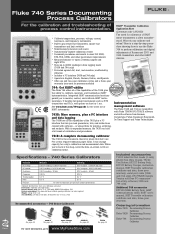
... Industrial Test Leads (2 sets), AC220 Test Clips (2 sets), TP220 Test Probes, BP7217 Battery Pack, BC7217 Battery Charger, instruction manual, NIST Traceable calibration certificate and data, three year warranty, serial port cable (743B and 744 only), DPC/TRACK Sample Version with free PC communication utility software (743B and 744 only). Ordering information Fluke-741B Documenting...
... Industrial Test Leads (2 sets), AC220 Test Clips (2 sets), TP220 Test Probes, BP7217 Battery Pack, BC7217 Battery Charger, instruction manual, NIST Traceable calibration certificate and data, three year warranty, serial port cable (743B and 744 only), DPC/TRACK Sample Version with free PC communication utility software (743B and 744 only). Ordering information Fluke-741B Documenting...
Fluke 744 Users Manual
Page 13
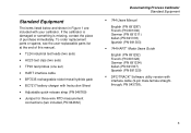
...the end of purchase immediately. If the calibrator is damaged or something is missing, contact the place of this manual. • TL24 industrial test leads (two sets) • AC20 test clips (two sets) • TP20 test probes (one set) • HART interface cable • BP7235... RTD measurement connections (two included, PN 944632) Documenting Process Calibrator Standard Equipment • 744 Users Manual English (PN 691287) French (PN 691300) German (PN 691311) Italian (PN 691318) Spanish (PN 691303) • 744 HART® Mode Users Guide English (PN 691292) French (PN 691326) German (PN...
...the end of purchase immediately. If the calibrator is damaged or something is missing, contact the place of this manual. • TL24 industrial test leads (two sets) • AC20 test clips (two sets) • TP20 test probes (one set) • HART interface cable • BP7235... RTD measurement connections (two included, PN 944632) Documenting Process Calibrator Standard Equipment • 744 Users Manual English (PN 691287) French (PN 691300) German (PN 691311) Italian (PN 691318) Spanish (PN 691303) • 744 HART® Mode Users Guide English (PN 691292) French (PN 691326) German (PN...
Fluke 744 Users Manual
Page 15
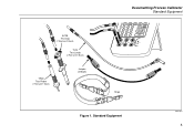
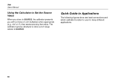
AC20 Test Clip (2 Red and 2 Black) TL24 Test Leads (2 Red and 2 Black) TP20 Test Probe (1 Red and 1 Black) Jumper (2 Black) Documenting Process Calibrator Standard Equipment V 7 4 V Hz 8 9 5 6 TC RTD CLEAR ( ZERO) 1 2 3 0 . Standard Equipment ot01f.eps 5 ENTER V RTD mA mA V RTD SOURCE 30V MAX MEAS 300V MAX TC Strap Figure 1.
AC20 Test Clip (2 Red and 2 Black) TL24 Test Leads (2 Red and 2 Black) TP20 Test Probe (1 Red and 1 Black) Jumper (2 Black) Documenting Process Calibrator Standard Equipment V 7 4 V Hz 8 9 5 6 TC RTD CLEAR ( ZERO) 1 2 3 0 . Standard Equipment ot01f.eps 5 ENTER V RTD mA mA V RTD SOURCE 30V MAX MEAS 300V MAX TC Strap Figure 1.
Fluke 744 Users Manual
Page 18
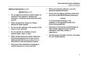
... shock or personal injury, adhere to the user; When you use the calibrator, inspect the insulating cover. The possibility of false readings can lead to the insulation surrounding the connectors. • Disconnect the power and discharge all highvoltage capacitors in doubt, have the calibrator serviced. •...missing plastic. Pay particular attention to electric shock and personal injury. 8 Keep your fingers away from the probe contacts. Check test lead continuity. 744 Users Manual Safety Information (cont) A Warning identifies conditions and actions that may be impaired.
... shock or personal injury, adhere to the user; When you use the calibrator, inspect the insulating cover. The possibility of false readings can lead to the insulation surrounding the connectors. • Disconnect the power and discharge all highvoltage capacitors in doubt, have the calibrator serviced. •...missing plastic. Pay particular attention to electric shock and personal injury. 8 Keep your fingers away from the probe contacts. Check test lead continuity. 744 Users Manual Safety Information (cont) A Warning identifies conditions and actions that may be impaired.
Fluke 744 Users Manual
Page 19
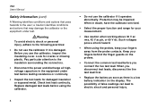
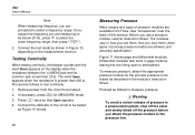
...to or disconnect it to another measure or source function. Safety Information (cont) Warning (cont) • Do not apply more than the Fluke model BE9005 Battery Eliminator. Documenting Process Calibrator Safety Information • When servicing the calibrator, use only specified replacement parts. • Do ...the process pressure line is shut off and depressurized before you connect it from the pressure module. • Disconnect test leads before testing resistance, continuity, diodes, or capacitance. • Use the proper terminals, function, and range for your measurements. 9
...to or disconnect it to another measure or source function. Safety Information (cont) Warning (cont) • Do not apply more than the Fluke model BE9005 Battery Eliminator. Documenting Process Calibrator Safety Information • When servicing the calibrator, use only specified replacement parts. • Do ...the process pressure line is shut off and depressurized before you connect it from the pressure module. • Disconnect test leads before testing resistance, continuity, diodes, or capacitance. • Use the proper terminals, function, and range for your measurements. 9
Fluke 744 Users Manual
Page 40
Remove power from Fluke. Connect the calibrator to the circuit to be tested. 2. Connect the test leads as shown in Figure 10, depending on the display when the resistance between the Ω MEAS jack and its Instruction Sheet. Testing Continuity When testing .... The word Open appears when the resistance is less than 400 Ω. Before you use them, how you zero them, what types of this manual. 744 Users Manual Note When measuring frequency, you are prompted to be tested as described in the module's Instruction Sheet.
Remove power from Fluke. Connect the calibrator to the circuit to be tested. 2. Connect the test leads as shown in Figure 10, depending on the display when the resistance between the Ω MEAS jack and its Instruction Sheet. Testing Continuity When testing .... The word Open appears when the resistance is less than 400 Ω. Before you use them, how you zero them, what types of this manual. 744 Users Manual Note When measuring frequency, you are prompted to be tested as described in the module's Instruction Sheet.

Fluke 744 Users Manual
Page 44
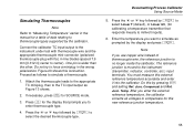
... input/output as follows: a. Table 5 summarizes the ranges and characteristics of the supported thermocouples. Attach the thermocouple leads to the appropriate TC miniplug, then to choose a setting for MEASURE mode. 3. Note If the calibrator and ... temperature using the u or d followed by e. 5. d. If necessary, press M for that parameter. Press the Done softkey or sto exit Setup mode. 6. 744 Users Manual Measuring Temperature Using Thermocouples The calibrator supports eleven standard thermocouples, each identified with an alpha character: E, N, J, K, T, B, R, S, C, L, or...
... input/output as follows: a. Table 5 summarizes the ranges and characteristics of the supported thermocouples. Attach the thermocouple leads to the appropriate TC miniplug, then to choose a setting for MEASURE mode. 3. Note If the calibrator and ... temperature using the u or d followed by e. 5. d. If necessary, press M for that parameter. Press the Done softkey or sto exit Setup mode. 6. 744 Users Manual Measuring Temperature Using Thermocouples The calibrator supports eleven standard thermocouples, each identified with an alpha character: E, N, J, K, T, B, R, S, C, L, or...
Fluke 744 Users Manual
Page 45
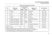
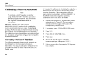
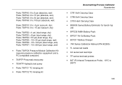
Thermocouple Types Accepted Type Positive Lead Material Positive Lead (H) Color ANSI* IEC** Negative Lead Material E Chromel Purple Violet Constantan N Ni-Cr-Si Orange Pink Ni-Si-Mg J Iron White Black ...Tungsten (26% Rhenium) L (DIN J) Iron Constantan U (DIN T) Copper Constantan *American National Standards Institute (ANSI) device negative lead (L) is always red. **International Electrotechnical Commission (IEC) device negative lead (L) is always white. *** Not an ANSI designation but a Hoskins Engineering Company designation. Specified Range (°C) -250 to 1000...
Thermocouple Types Accepted Type Positive Lead Material Positive Lead (H) Color ANSI* IEC** Negative Lead Material E Chromel Purple Violet Constantan N Ni-Cr-Si Orange Pink Ni-Si-Mg J Iron White Black ...Tungsten (26% Rhenium) L (DIN J) Iron Constantan U (DIN T) Copper Constantan *American National Standards Institute (ANSI) device negative lead (L) is always red. **International Electrotechnical Commission (IEC) device negative lead (L) is always white. *** Not an ANSI designation but a Hoskins Engineering Company designation. Specified Range (°C) -250 to 1000...
Fluke 744 Users Manual
Page 56
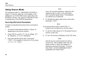
... current function to source 5.0 V dc, press v 5 . 0 e. 46 Note If you specify is not in the present source function, press c. 6. 744 Users Manual Using Source Mode The operating mode (i.e., MEASURE, SOURCE) is shown in SOURCE mode to change the output value enter a new value and press... the Loop Power function accessible from Setup mode. You must be in a reverse-video bar on the source function. 2. Connect the test leads as follows: 1. This is shown. Sourcing Electrical Parameters To select an electrical sourcing function, proceed as shown in which the calibrator is powering...
... current function to source 5.0 V dc, press v 5 . 0 e. 46 Note If you specify is not in the present source function, press c. 6. 744 Users Manual Using Source Mode The operating mode (i.e., MEASURE, SOURCE) is shown in SOURCE mode to change the output value enter a new value and press... the Loop Power function accessible from Setup mode. You must be in a reverse-video bar on the source function. 2. Connect the test leads as follows: 1. This is shown. Sourcing Electrical Parameters To select an electrical sourcing function, proceed as shown in which the calibrator is powering...
Fluke 744 Users Manual
Page 65
... compensate for SOURCE mode. 3. After you to the TC input/output as follows to the instrument (transmitter, indicator, controller, etc.) input terminals. Attach the thermocouple leads to the appropriate TC miniplug, then to enter thermocouple type. 4. Press t for the display that responds linearly to millivolt inputs). 6. Junc. Compensat and Ref. One...
... compensate for SOURCE mode. 3. After you to the TC input/output as follows to the instrument (transmitter, indicator, controller, etc.) input terminals. Attach the thermocouple leads to the appropriate TC miniplug, then to enter thermocouple type. 4. Press t for the display that responds linearly to millivolt inputs). 6. Junc. Compensat and Ref. One...
Fluke 744 Users Manual
Page 78
...mode. 3. Generating "As Found" Test Data The following example shows how to select the thermocouple type, then press e. 7. Switch tests. 744 Users Manual Calibrating a Process Instrument Note To calibrate a HART-capable transmitter using a host computer and compatible application software. Just go back to... the instrument under test as found data for Delta-P and 1 Pt. Connect the test leads to MEASUREMENT or SOURCE mode and change the operating parameters before it is calibrated.) The calibrator runs preloaded tasks (procedures) that ...
...mode. 3. Generating "As Found" Test Data The following example shows how to select the thermocouple type, then press e. 7. Switch tests. 744 Users Manual Calibrating a Process Instrument Note To calibrate a HART-capable transmitter using a host computer and compatible application software. Just go back to... the instrument under test as found data for Delta-P and 1 Pt. Connect the test leads to MEASUREMENT or SOURCE mode and change the operating parameters before it is calibrated.) The calibrator runs preloaded tasks (procedures) that ...
Fluke 744 Users Manual
Page 87
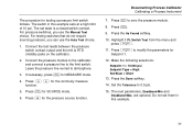
... switches, you can use the Manual Test choice. If necessary, press M for SOURCE mode. 6. Do not set state is a closed switch contact. Connect the test leads between the pressure switch contact output and the mA Ω RTD (middle) jacks on the calibrator. 2. Press c to the limit switch. The next parameters, Deadband...
... switches, you can use the Manual Test choice. If necessary, press M for SOURCE mode. 6. Do not set state is a closed switch contact. Connect the test leads between the pressure switch contact output and the mA Ω RTD (middle) jacks on the calibrator. 2. Press c to the limit switch. The next parameters, Deadband...
Fluke 744 Users Manual
Page 88
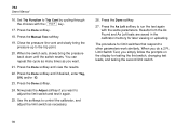
... the same parameters. Results from the As Found and As Left tests are saved in the calibrator memory for testing the first switch, changing test leads, and testing the second limit switch. 78 Limit Switch Test, you do a 2 Pt. Close the pressure line vent and slowly bring the pressure back down... trip point. 20. The procedure for limit switches that respond to adjust the limit switch and test it again. 25. Press the Done softkey. 24. 744 Users Manual 16. Press the Manual Test softkey. 19. When the switch sets, slowly bring the pressure up to run the test again with the...
... the same parameters. Results from the As Found and As Left tests are saved in the calibrator memory for testing the first switch, changing test leads, and testing the second limit switch. 78 Limit Switch Test, you do a 2 Pt. Close the pressure line vent and slowly bring the pressure back down... trip point. 20. The procedure for limit switches that respond to adjust the limit switch and test it again. 25. Press the Done softkey. 24. 744 Users Manual 16. Press the Manual Test softkey. 19. When the switch sets, slowly bring the pressure up to run the test again with the...
Fluke 744 Users Manual
Page 89
... the process input to the control wires in place of a transmitter for diagnostic purposes only. If necessary, press M for the process input. 79 Connect test leads from the appropriate calibrator SOURCE jacks to the appropriate calibrator MEASURE jacks or input connector. 5. Press the appropriate function key for MEASURE mode. 6. Caution Transmitter...
... the process input to the control wires in place of a transmitter for diagnostic purposes only. If necessary, press M for the process input. 79 Connect test leads from the appropriate calibrator SOURCE jacks to the appropriate calibrator MEASURE jacks or input connector. 5. Press the appropriate function key for MEASURE mode. 6. Caution Transmitter...
Fluke 744 Users Manual
Page 98
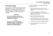
744 Users Manual Using the Calculator to Set the Source Value When you store to use for many different applications. 88 Quick Guide to Applications The following figures show test lead connections and which calibrator function to SOURCE, the calibrator presents you with a choice of -range values to SOURCE. The calibrator ignores attempts to store out-of unit multipliers when appropriate (e.g., mV or V), then starts sourcing that value.
744 Users Manual Using the Calculator to Set the Source Value When you store to use for many different applications. 88 Quick Guide to Applications The following figures show test lead connections and which calibrator function to SOURCE, the calibrator presents you with a choice of -range values to SOURCE. The calibrator ignores attempts to store out-of unit multipliers when appropriate (e.g., mV or V), then starts sourcing that value.
Fluke 744 Users Manual
Page 113
... pressure calibration equipment and a PC compatible computer) • 700PTP Pneumatic test pump • 700HTP Hydraulic test pump • Fluke-700TC1 TC miniplug kit • Fluke-700TC2 TC miniplug kit Documenting Process Calibrator Accessories • C781 Soft Carrying Case • C789 Soft Carrying Case • C700... Ni-Cd Battery Pack • BC7217 Battery Charger • 74X Series Calibration Manual (PN 602505) • TL series test leads • AC series test lead clips • TP series test lead probes • 80T-IR Infrared Temperature Probe, -18°C to 260°C 103
... pressure calibration equipment and a PC compatible computer) • 700PTP Pneumatic test pump • 700HTP Hydraulic test pump • Fluke-700TC1 TC miniplug kit • Fluke-700TC2 TC miniplug kit Documenting Process Calibrator Accessories • C781 Soft Carrying Case • C789 Soft Carrying Case • C700... Ni-Cd Battery Pack • BC7217 Battery Charger • 74X Series Calibration Manual (PN 602505) • TL series test leads • AC series test lead clips • TP series test lead probes • 80T-IR Infrared Temperature Probe, -18°C to 260°C 103
