Fluke 744 Users Manual
Page 4
744 Users Manual Displaying the Date and Time 24 Using the Backlight 26 Personalizing the Calibrator 26 Using Measure Mode...28 Measurement Ranges 28 Measuring Electrical ... the 700-IV Current Shunt 44 Damping Your Measurements 44 Using Source Mode ...46 Sourcing Electrical Parameters 46 Simulating a 4 to 20 mA Transmitter 48 Supplying Loop Power 50 Sourcing Pressure...52 Simulating Thermocouples 55 Simulating RTDs ...56 Source Scale...59 Linear-Responding Transmitters 59 Square-Law Process Variables 59 Stepping and Ramping...
744 Users Manual Displaying the Date and Time 24 Using the Backlight 26 Personalizing the Calibrator 26 Using Measure Mode...28 Measurement Ranges 28 Measuring Electrical ... the 700-IV Current Shunt 44 Damping Your Measurements 44 Using Source Mode ...46 Sourcing Electrical Parameters 46 Simulating a 4 to 20 mA Transmitter 48 Supplying Loop Power 50 Sourcing Pressure...52 Simulating Thermocouples 55 Simulating RTDs ...56 Source Scale...59 Linear-Responding Transmitters 59 Square-Law Process Variables 59 Stepping and Ramping...
Fluke 744 Users Manual
Page 6
744 Users Manual Calibration Data ...99 In Case of Difficulty 99 Service Center Calibration or Repair 100 Replacement Parts ...101 Accessories...102 Specifications...104 DC Voltage ... Measurement 108 DC Voltage Output ...109 DC Current Output ...110 Resistance Sourcing 111 Frequency Sourcing 112 Temperature, Thermocouples 113 Temperature, Resistance Temperature Detectors 116 Loop Power Supply 118 Top and Bottom Limits of Ranges with Auto Range On 119 General Specifications 121 Index ...125 iv
744 Users Manual Calibration Data ...99 In Case of Difficulty 99 Service Center Calibration or Repair 100 Replacement Parts ...101 Accessories...102 Specifications...104 DC Voltage ... Measurement 108 DC Voltage Output ...109 DC Current Output ...110 Resistance Sourcing 111 Frequency Sourcing 112 Temperature, Thermocouples 113 Temperature, Resistance Temperature Detectors 116 Loop Power Supply 118 Top and Bottom Limits of Ranges with Auto Range On 119 General Specifications 121 Index ...125 iv
Fluke 744 Users Manual
Page 10
......94 33. Connections for Simulating an RTD 58 22. Connections for Supplying Loop Power 51 19. Calibrating a Thermocouple Temperature Transmitter 70 24. Connections for ...Sourcing Pressure 54 20. Limit Switch Terminology...76 25. Checking a Vortex Sheeding Flowmeter 97 37. Calibrating a Current-to Current Transmitter 96 36. Calibrating a mV to -Pressure (I ) Transmitter 95 35. Checking a Tachometer...94 34. Sourcing Resistance...93 32. 744...
......94 33. Connections for Simulating an RTD 58 22. Connections for Supplying Loop Power 51 19. Calibrating a Thermocouple Temperature Transmitter 70 24. Connections for ...Sourcing Pressure 54 20. Limit Switch Terminology...76 25. Checking a Vortex Sheeding Flowmeter 97 37. Calibrating a Current-to Current Transmitter 96 36. Calibrating a mV to -Pressure (I ) Transmitter 95 35. Checking a Tachometer...94 34. Sourcing Resistance...93 32. 744...
Fluke 744 Users Manual
Page 22
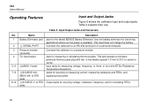
... resistance and RTDs, and supplying loop power. Pressure module connector TC input/output wMEAS V jacks wSOURCE mA, MEAS mA Ω RTD jacks wSOURCE V Ω RTD jacks Connects the calibrator to center. Jacks for bench-top applications where ac line power is available. Jack for ...voltage, frequency, or three- or four-wire RTDs (Resistance Temperature Detectors). Table 2. Input jacks for the Model BE9005 Battery Eliminator. 744 Users Manual Operating Features Input and Output Jacks Figure 5 shows the calibrator input and output jacks. This jack accepts a miniature polarized ...
... resistance and RTDs, and supplying loop power. Pressure module connector TC input/output wMEAS V jacks wSOURCE mA, MEAS mA Ω RTD jacks wSOURCE V Ω RTD jacks Connects the calibrator to center. Jacks for bench-top applications where ac line power is available. Jack for ...voltage, frequency, or three- or four-wire RTDs (Resistance Temperature Detectors). Table 2. Input jacks for the Model BE9005 Battery Eliminator. 744 Users Manual Operating Features Input and Output Jacks Figure 5 shows the calibrator input and output jacks. This jack accepts a miniature polarized ...

Fluke 744 Users Manual
Page 59
Documenting Process Calibrator Using Source Mode 744 DOCUMENTING PROCESS CALIBRATOR + +24 Loop Power Supply Red MEAS SOURCE mA SETUP V V Hz TC RTD 7 8 9 CLEAR ( ZERO) 4 5 6 1 2 3 0. Figure 17. ENTER V mA mA V RTD RTD CAT 30V MAX SOURCE 30V MEAS 30V 300V MAX TC MAX MAX Black UUT - Connections for Simulating a 4 to 20 mA Transmitter ot17c.eps 49
Documenting Process Calibrator Using Source Mode 744 DOCUMENTING PROCESS CALIBRATOR + +24 Loop Power Supply Red MEAS SOURCE mA SETUP V V Hz TC RTD 7 8 9 CLEAR ( ZERO) 4 5 6 1 2 3 0. Figure 17. ENTER V mA mA V RTD RTD CAT 30V MAX SOURCE 30V MEAS 30V 300V MAX TC MAX MAX Black UUT - Connections for Simulating a 4 to 20 mA Transmitter ot17c.eps 49
Fluke 744 Users Manual
Page 60
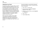
The 28 V setting supplies enough current for Setup mode. 2. A typical transmitter must have 11 V minimum in addition to sourcing and measuring the current loop. This means that following Loop Power, Disabled is enabled, the mA (middle column) jacks are two or fewer devices on a typical ... the 24 V setting if there are dedicated to the twowire transmitter but uses more battery power. Press e. 3. 744 Users Manual Supplying Loop Power The calibrator supplies loop power at 20 mA. to source loop power: 1. Proceed as Figure 18 shows. Note that the SOURCE mA, measure RTD, and measure...
The 28 V setting supplies enough current for Setup mode. 2. A typical transmitter must have 11 V minimum in addition to sourcing and measuring the current loop. This means that following Loop Power, Disabled is enabled, the mA (middle column) jacks are two or fewer devices on a typical ... the 24 V setting if there are dedicated to the twowire transmitter but uses more battery power. Press e. 3. 744 Users Manual Supplying Loop Power The calibrator supplies loop power at 20 mA. to source loop power: 1. Proceed as Figure 18 shows. Note that the SOURCE mA, measure RTD, and measure...

Fluke 744 Users Manual
Page 61
744 DOCUMENTING PROCESS CALIBRATOR Documenting Process Calibrator Using Source Mode MEAS SOURCE mA SETUP V V Hz TC RTD 7 8 9 CLEAR ( ZERO) 4 5 6 1 2 3 0. ENTER V mA mA V RTD RTD CAT 30V MAX SOURCE 30V MEAS 30V 300V MAX TC MAX MAX Red TEST DC PWR - ++ - +- Connections for Supplying Loop Power ot18c.eps 51 Black Figure 18.
744 DOCUMENTING PROCESS CALIBRATOR Documenting Process Calibrator Using Source Mode MEAS SOURCE mA SETUP V V Hz TC RTD 7 8 9 CLEAR ( ZERO) 4 5 6 1 2 3 0. ENTER V mA mA V RTD RTD CAT 30V MAX SOURCE 30V MEAS 30V 300V MAX TC MAX MAX Red TEST DC PWR - ++ - +- Connections for Supplying Loop Power ot18c.eps 51 Black Figure 18.

Fluke 744 Users Manual
Page 80
ENTER V mA RTD 30V MAX SOURCE 30V MAX mA RTD CAT MEAS 30V MAX V 300V MAX Red TC Miniplug TEST DC PWR - ++ +- 744 Users Manual 744 DOCUMENTING PROCESS CALIBRATOR Color depends on type of TC MEAS SOURCE mA SETUP V V Hz TC RTD 7 8 9 CLEAR ( ZERO) 4 5 6 1 2 3 0 . Calibrating a Thermocouple Temperature Transmitter 70 ot23c.eps Original Circuit Wiring Power - Supply + Black Figure 23.
ENTER V mA RTD 30V MAX SOURCE 30V MAX mA RTD CAT MEAS 30V MAX V 300V MAX Red TC Miniplug TEST DC PWR - ++ +- 744 Users Manual 744 DOCUMENTING PROCESS CALIBRATOR Color depends on type of TC MEAS SOURCE mA SETUP V V Hz TC RTD 7 8 9 CLEAR ( ZERO) 4 5 6 1 2 3 0 . Calibrating a Thermocouple Temperature Transmitter 70 ot23c.eps Original Circuit Wiring Power - Supply + Black Figure 23.

Fluke 744 Users Manual
Page 90
...for the current output choice. 9. It is measuring the process input and sourcing the control signal output proportional to a current loop that has a power supply, select Simulate Transmitter for MEASURE/SOURCE mode. 11. Select a source value, e.g., 4 mA. 10. Press Done. 15. The calibrator is ...or √ for SOURCE mode. 8. Press More Choices until the Transmitter Mode softkey appears. 12. Press M for the transfer function. 14. 744 Users Manual 7. Set the 0% and 100% values for the control output (e.g., v or m). To change any of the Transmitter mode parameters, ...
...for the current output choice. 9. It is measuring the process input and sourcing the control signal output proportional to a current loop that has a power supply, select Simulate Transmitter for MEASURE/SOURCE mode. 11. Select a source value, e.g., 4 mA. 10. Press Done. 15. The calibrator is ...or √ for SOURCE mode. 8. Press More Choices until the Transmitter Mode softkey appears. 12. Press M for the transfer function. 14. 744 Users Manual 7. Set the 0% and 100% values for the control output (e.g., v or m). To change any of the Transmitter mode parameters, ...

Fluke 744 Users Manual
Page 102
Original Circuit Wiring Power - Supply + Black Figure 29. Measuring the Output Current of a Transmitter 92 ot29c.eps ENTER V mA mA V RTD RTD CAT 30V MAX SOURCE 30V MEAS 30V 300V MAX TC MAX MAX Red TEST DC PWR - ++ +- 744 Users Manual 744 DOCUMENTING PROCESS CALIBRATOR Measure mA Loop Power Disabled MEAS SOURCE mA SETUP V V Hz TC RTD 7 8 9 CLEAR ( ZERO) 4 5 6 1 2 3 0 .
Original Circuit Wiring Power - Supply + Black Figure 29. Measuring the Output Current of a Transmitter 92 ot29c.eps ENTER V mA mA V RTD RTD CAT 30V MAX SOURCE 30V MEAS 30V 300V MAX TC MAX MAX Red TEST DC PWR - ++ +- 744 Users Manual 744 DOCUMENTING PROCESS CALIBRATOR Measure mA Loop Power Disabled MEAS SOURCE mA SETUP V V Hz TC RTD 7 8 9 CLEAR ( ZERO) 4 5 6 1 2 3 0 .
Fluke 744 Users Manual
Page 128
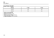
744 Users Manual Loop Power Supply Setting 24 Volt 28 Volt Short circuit protected Maximum Current: 22 mA Maximum Input Voltage: 30 V dc Output Resistance: 250 Ω nominal 1 Year 5% 5% 2 Year 5% 5% 118
744 Users Manual Loop Power Supply Setting 24 Volt 28 Volt Short circuit protected Maximum Current: 22 mA Maximum Input Voltage: 30 V dc Output Resistance: 250 Ω nominal 1 Year 5% 5% 2 Year 5% 5% 118


