
FE 51 & 52 II Users Manual
Page 1
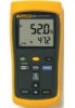
Printed in USA All product names are trademarks of their respective companies. Users Manual ® 51 & 52 Series II Thermometer English September 1999 Rev.1, 6/01 © 1999-2001 Fluke Corporation, All rights reserved.
Printed in USA All product names are trademarks of their respective companies. Users Manual ® 51 & 52 Series II Thermometer English September 1999 Rev.1, 6/01 © 1999-2001 Fluke Corporation, All rights reserved.
FE 51 & 52 II Users Manual
Page 4
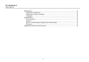
51 & 52 Series II Users Manual Maintenance...13 Replacing the Batteries 13 Cleaning the Case and Holster 13 Calibration ...13 Specifications ...13 Environmental...13 General...14 80 PK-1 Thermocouple (supplied with thermometer 14 Electrical...14 Replacement Parts and Accessories 15 ii
51 & 52 Series II Users Manual Maintenance...13 Replacing the Batteries 13 Cleaning the Case and Holster 13 Calibration ...13 Specifications ...13 Environmental...13 General...14 80 PK-1 Thermocouple (supplied with thermometer 14 Electrical...14 Replacement Parts and Accessories 15 ii
FE 51 & 52 II Users Manual
Page 6
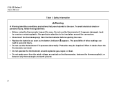
..., or dust. • Do not apply more than the rated voltage, as the battery indicator (B) appears. The possibility of false readings can lead to the user. When in doubt, have the thermometer serviced. • Do not operate the thermometer around the connectors. • Disconnect the thermocouple(s) from the thermometer before opening... identifies conditions and actions that pose hazards to personal injury. • Do not use the thermometer if it operates abnormally. Protection may be impaired. 51 & 52 Series II Users Manual Table 1.
..., or dust. • Do not apply more than the rated voltage, as the battery indicator (B) appears. The possibility of false readings can lead to the user. When in doubt, have the thermometer serviced. • Do not operate the thermometer around the connectors. • Disconnect the thermocouple(s) from the thermometer before opening... identifies conditions and actions that pose hazards to personal injury. • Do not use the thermometer if it operates abnormally. Protection may be impaired. 51 & 52 Series II Users Manual Table 1.
FE 51 & 52 II Users Manual
Page 8
... functions of the buttons. P Complies with relevant Canadian Standards Association directives. Battery. International Symbols W M Refer to Models 51 and 52 unless otherwise indicated. To become familiar with the thermometer, study the following sections. 4 Getting Started Everything in this Users Manual applies both to the manual for information about this feature. 51 & 52 Series II Users Manual Table 2.
... functions of the buttons. P Complies with relevant Canadian Standards Association directives. Battery. International Symbols W M Refer to Models 51 and 52 unless otherwise indicated. To become familiar with the thermometer, study the following sections. 4 Getting Started Everything in this Users Manual applies both to the manual for information about this feature. 51 & 52 Series II Users Manual Table 2.
FE 51 & 52 II Users Manual
Page 10
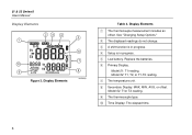
C A shift function is in progress. E Low battery. Model 52: T1, T2, or T1-T2 reading. G The temperature unit. Model 52: T1or T2 reading. J Time Display: The elapsed time. 6 F Primary Display. Display Elements A The thermocouple measurement includes an offset. Replace the batteries. I The thermocouple...." B The displayed readings do not change. Model 51: T1 reading. H Secondary Display: MAX, MIN, AVG, or offset. D Setup is in progress. 51 & 52 Series II Users Manual Display Elements 23 4 1 10 9 Figure 2. Display Elements xx 5 6 7 8 aas02f.eps Table 4.
C A shift function is in progress. E Low battery. Model 52: T1, T2, or T1-T2 reading. G The temperature unit. Model 52: T1or T2 reading. J Time Display: The elapsed time. 6 F Primary Display. Display Elements A The thermocouple measurement includes an offset. Replace the batteries. I The thermocouple...." B The displayed readings do not change. Model 51: T1 reading. H Secondary Display: MAX, MIN, AVG, or offset. D Setup is in progress. 51 & 52 Series II Users Manual Display Elements 23 4 1 10 9 Figure 2. Display Elements xx 5 6 7 8 aas02f.eps Table 4.
FE 51 & 52 II Users Manual
Page 12
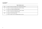
Press N to store the displayed setting in memory. 8 Press E again to decrease the displayed setting. Press N to scroll to the Setup option you want to change . 51 & 52 Series II Users Manual D K N E Table 5. Buttons (cont.) Press D to start or exit Setup. (See "Changing Setup Options.") Press K to scroll to the Setup option you want to change . Press E to increase the displayed setting. Press K to enter a Setup option.
Press N to store the displayed setting in memory. 8 Press E again to decrease the displayed setting. Press N to scroll to the Setup option you want to change . 51 & 52 Series II Users Manual D K N E Table 5. Buttons (cont.) Press D to start or exit Setup. (See "Changing Setup Options.") Press K to scroll to the Setup option you want to change . Press E to increase the displayed setting. Press K to enter a Setup option.
FE 51 & 52 II Users Manual
Page 14
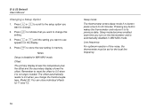
... it is no button press occurs for 20 minutes. Press K or N to scroll to the setup option you want to change the thermocouple type. Model 52: You can store individual offsets for the local line frequency. 10 Line frequency: For optimum rejection of line noise, the thermometer must be set for... in MIN MAX mode. Press K or N until the setting you change this setting. 3. Sleep mode becomes enabled each time you turn on the display. 4. 51 & 52 Series II Users Manual Changing a Setup Option 1. Notes Setup is automatically disabled in memory.
... it is no button press occurs for 20 minutes. Press K or N to scroll to the setup option you want to change the thermocouple type. Model 52: You can store individual offsets for the local line frequency. 10 Line frequency: For optimum rejection of line noise, the thermometer must be set for... in MIN MAX mode. Press K or N until the setting you change this setting. 3. Sleep mode becomes enabled each time you turn on the display. 4. 51 & 52 Series II Users Manual Changing a Setup Option 1. Notes Setup is automatically disabled in memory.
FE 51 & 52 II Users Manual
Page 16
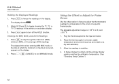
Model 52: Press T to toggle showing the T1, T2, or T1-T2 readings in Setup to adjust the thermometer's readings to compensate for Probe Errors Use the ... h again to exit MIN MAX mode. Place the thermocouple in a known, stable temperature environment (such as an ice bath or a dry well calibrator). 3. 51 & 52 Series II Users Manual Holding the Displayed Readings 1. Press G, M (CANCEL) to turn off the HOLD function. The display shows H. 2. Press M to Adjust for the errors of a specific thermocouple...
Model 52: Press T to toggle showing the T1, T2, or T1-T2 readings in Setup to adjust the thermometer's readings to compensate for Probe Errors Use the ... h again to exit MIN MAX mode. Place the thermocouple in a known, stable temperature environment (such as an ice bath or a dry well calibrator). 3. 51 & 52 Series II Users Manual Holding the Displayed Readings 1. Press G, M (CANCEL) to turn off the HOLD function. The display shows H. 2. Press M to Adjust for the errors of a specific thermocouple...
FE 51 & 52 II Users Manual
Page 18
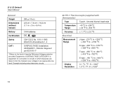
.... 1010.1 1992 EN 61010 Amendments 1, 2 CAT I OVERVOLTAGE (Installation) CATEGORY I, Pollution Degree 2 per IEC1010-1* * Refers to the level of Impulse Withstand Voltage protection provided. 51 & 52 Series II Users Manual General Weight 280 g (10 oz) Dimensions (without holster) 2.8 cm × 7.8 cm × 16.2 cm (1.1 in × 3 in × 6.4 in which measures are taken to...
.... 1010.1 1992 EN 61010 Amendments 1, 2 CAT I OVERVOLTAGE (Installation) CATEGORY I, Pollution Degree 2 per IEC1010-1* * Refers to the level of Impulse Withstand Voltage protection provided. 51 & 52 Series II Users Manual General Weight 280 g (10 oz) Dimensions (without holster) 2.8 cm × 7.8 cm × 16.2 cm (1.1 in × 3 in × 6.4 in which measures are taken to...

FE 51 & 52 II Users Manual
Page 20
51 & 52 Series II Users Manual 16
51 & 52 Series II Users Manual 16


