Product Manual
Page 4
...Regional Voltage 2-1 Connect to Mains Power 2-3 Set the Handle Position 2-4 Power On and Standby 2-5 Warm-Up the Product 2-6 Configure the Product 2-6 Input Module and Relay Card Installation 2-7 Set Up Security 2-10 3 Input and Channel Configuration 3-1 Introduction ...3-1 Input Wiring...3-1 The Universal Input Module 3-1 Wiring Safety and Considerations 3-2 3-Wire and 4-Wire Sense Input Configuration 3-3 Input Types and Wiring Diagrams 3-5 Input Wiring Instructions 3-6 Channel Configuration 3-7 About Channel Numbers 3-7 Basic Channel Operations 3-10 Open the Channel Setup...
...Regional Voltage 2-1 Connect to Mains Power 2-3 Set the Handle Position 2-4 Power On and Standby 2-5 Warm-Up the Product 2-6 Configure the Product 2-6 Input Module and Relay Card Installation 2-7 Set Up Security 2-10 3 Input and Channel Configuration 3-1 Introduction ...3-1 Input Wiring...3-1 The Universal Input Module 3-1 Wiring Safety and Considerations 3-2 3-Wire and 4-Wire Sense Input Configuration 3-3 Input Types and Wiring Diagrams 3-5 Input Wiring Instructions 3-6 Channel Configuration 3-7 About Channel Numbers 3-7 Basic Channel Operations 3-10 Open the Channel Setup...

Product Manual
Page 5
... 3-32 Rate of Change 3-32 NPLC ...3-33 Input Impedance 3-33 Bandwidth ...3-33 Display As ...3-33 Open Detect 3-33 4 Scan/Monitor, Record, and Data 4-1 Introduction ...4-1 Scan ...4-1 About Scan Timing and Sampling 4-3 Configure a Scan 4-5 Trigger Type 4-6 Auto Recording 4-7 File Destination 4-7 Sample Rate 4-7 Data Security 4-8 Temperature Unit 4-9 Align Channels 4-9 Automatic Power Loss Scan Resume 4-10 Basic Scan Procedures 4-10 Start a Scan 4-10 View Scan Data and...
... 3-32 Rate of Change 3-32 NPLC ...3-33 Input Impedance 3-33 Bandwidth ...3-33 Display As ...3-33 Open Detect 3-33 4 Scan/Monitor, Record, and Data 4-1 Introduction ...4-1 Scan ...4-1 About Scan Timing and Sampling 4-3 Configure a Scan 4-5 Trigger Type 4-6 Auto Recording 4-7 File Destination 4-7 Sample Rate 4-7 Data Security 4-8 Temperature Unit 4-9 Align Channels 4-9 Automatic Power Loss Scan Resume 4-10 Basic Scan Procedures 4-10 Start a Scan 4-10 View Scan Data and...
Product Manual
Page 7
... 3-10. Math Channel Configuration 3-28 4-1. Scan Statistics...4-12 4-5. Rear-Panel Features 1-5 1-3. Troublehooti ng Chart 7-17 v MyFlukeStore Shop for Fluke products online at: www. .com 1.888.610.7664 Statistics ...5-4 6-1. Thermocouple Channel Configuration 3-19 3-7. Fuses ...6-1 6-2. Channel Setup Menu 3-10 3-4. Frequency Channel Configuration 3-20 3-8. Scan Data Memory Usage 4-15 5-1. List of Tables Table Title Page 1-1. Math Channel Formulas 3-26 3-12. User-Replaceable Parts and Accessories 6-5 7-1.
... 3-10. Math Channel Configuration 3-28 4-1. Scan Statistics...4-12 4-5. Rear-Panel Features 1-5 1-3. Troublehooti ng Chart 7-17 v MyFlukeStore Shop for Fluke products online at: www. .com 1.888.610.7664 Statistics ...5-4 6-1. Thermocouple Channel Configuration 3-19 3-7. Fuses ...6-1 6-2. Channel Setup Menu 3-10 3-4. Frequency Channel Configuration 3-20 3-8. Scan Data Memory Usage 4-15 5-1. List of Tables Table Title Page 1-1. Math Channel Formulas 3-26 3-12. User-Replaceable Parts and Accessories 6-5 7-1.

Product Manual
Page 9
... can be viewed on the types and ranges of -change. View the measurement value or the statistics of the Product include: • Scan - fChapter 1 Product Overview and Specifications Introduction This chapter supplies information about the Product, the manual set, safety information, contact information, and specifications. Users can be manually controlled from the front panel or triggered with a variety of the unit with a USB drive or...
... can be viewed on the types and ranges of -change. View the measurement value or the statistics of the Product include: • Scan - fChapter 1 Product Overview and Specifications Introduction This chapter supplies information about the Product, the manual set, safety information, contact information, and specifications. Users can be manually controlled from the front panel or triggered with a variety of the unit with a USB drive or...
Product Manual
Page 12
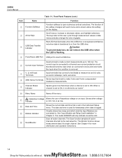
... when the USB drive is recognized and flashes red when data is logged. The model 2638A/05 will only indicate one active slot. See Chapter 4 for more information and operation instructions. 1-4 MyFlukeStore Shop for timestamps when data is transferred to as "active". Menu Name Name of the menu. X Hazardous Voltage Warns the user of a single channel. Red LED that connect to test...
... when the USB drive is recognized and flashes red when data is logged. The model 2638A/05 will only indicate one active slot. See Chapter 4 for more information and operation instructions. 1-4 MyFlukeStore Shop for timestamps when data is transferred to as "active". Menu Name Name of the menu. X Hazardous Voltage Warns the user of a single channel. Red LED that connect to test...

Product Manual
Page 13
... scan data, measurements made with the front-panel inputs. See "Set the Regional Voltage" in Chapter 2. When recording, the key illuminates and "RECORDING" shows on how to customize the Product. Menu contains many user-configurable settings to wire and configure a channel. See Chapter 4 for DMM operation instructions. In addition to unlock. See Chapter 5 for more information and operation instructions. 1 Product Overview and Specifications Front...
... scan data, measurements made with the front-panel inputs. See "Set the Regional Voltage" in Chapter 2. When recording, the key illuminates and "RECORDING" shows on how to customize the Product. Menu contains many user-configurable settings to wire and configure a channel. See Chapter 4 for DMM operation instructions. In addition to unlock. See Chapter 5 for more information and operation instructions. 1 Product Overview and Specifications Front...
Product Manual
Page 14
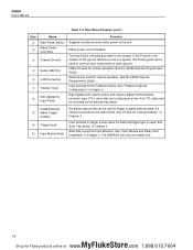
.... See Scan Test Setup" in Chapter 3. Trigger Input Input terminal to trigger a scan when the External trigger type is internally grounded to the unit. 2638A Users Manual Table 1-2. USB port used . Rear-Panel Features (cont.) Item Name Main Power Switch Mains Power Connector Chassis Ground Serial USB Port LAN Connection Totalizer Input DIO (Digital I/O Input Ports) Function Supplies and disconnects mains power to the chassis...
.... See Scan Test Setup" in Chapter 3. Trigger Input Input terminal to trigger a scan when the External trigger type is internally grounded to the unit. 2638A Users Manual Table 1-2. USB port used . Rear-Panel Features (cont.) Item Name Main Power Switch Mains Power Connector Chassis Ground Serial USB Port LAN Connection Totalizer Input DIO (Digital I/O Input Ports) Function Supplies and disconnects mains power to the chassis...
Product Manual
Page 15
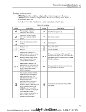
... this product as category 9 "Monitoring and Control Instrumentation" product. This product complies with the requirements of the building's low-voltage MAINS installation. CAT III Measurement Category III is applicable to test and measuring circuits connected directly to utilization points (socket outlets and similar points) of symbols used in the WEEE Directive Annex I, this manual and on the Product. P Product conforms...
... this product as category 9 "Monitoring and Control Instrumentation" product. This product complies with the requirements of the building's low-voltage MAINS installation. CAT III Measurement Category III is applicable to test and measuring circuits connected directly to utilization points (socket outlets and similar points) of symbols used in the WEEE Directive Annex I, this manual and on the Product. P Product conforms...

Product Manual
Page 16
... access to a protective earth ground. Look for the measurement. • Use only cables with correct voltage ratings. • Do not use the Product. 2638A Users Manual WXWarning To prevent possible electrical shock, fire, or personal injury: • Read all safety information before you use the Product. • Carefully read all instructions. • Use the Product only as specified, or the protection supplied by the...
... access to a protective earth ground. Look for the measurement. • Use only cables with correct voltage ratings. • Do not use the Product. 2638A Users Manual WXWarning To prevent possible electrical shock, fire, or personal injury: • Read all safety information before you use the Product. • Carefully read all instructions. • Use the Product only as specified, or the protection supplied by the...
Product Manual
Page 18
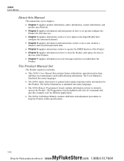
... product specifications. • Chapter 2 supplies information and instructions on how to set includes: • This 2638A Users Manual that contains feature information, operation instructions, and basic user maintenance and troubleshooting information. The Product Manual Set The Product manual set up and configure the Product for first time use. • Chapter 3 supplies instructions on how to wire inputs to the Input Module then configure the associated channel. • Chapter 4 supplies information and instructions on...
... product specifications. • Chapter 2 supplies information and instructions on how to set includes: • This 2638A Users Manual that contains feature information, operation instructions, and basic user maintenance and troubleshooting information. The Product Manual Set The Product manual set up and configure the Product for first time use. • Chapter 3 supplies instructions on how to wire inputs to the Input Module then configure the associated channel. • Chapter 4 supplies information and instructions on...

Product Manual
Page 19
2638A Users Manual General Specifications Mains Voltage 100 V Setting 90 V to 110 V 120 V Setting 108 V to 132 V 220 V Setting 198 V to 242 V 240 V Setting 216 V to 264 V Frequency 47 Hz to 440 Hz Power Consumption 36 VA peak (24 W average) Environment Temperature Operating 0 °C to 50 °C Full accuracy 18 °C to 28 °C Storage 20 °C to 70 °C Warm-up 1 hour to full accuracy specifications Relative Humidity (non-condensing) Operating 0 °C to 28 °C
2638A Users Manual General Specifications Mains Voltage 100 V Setting 90 V to 110 V 120 V Setting 108 V to 132 V 220 V Setting 198 V to 242 V 240 V Setting 216 V to 264 V Frequency 47 Hz to 440 Hz Power Consumption 36 VA peak (24 W average) Environment Temperature Operating 0 °C to 50 °C Full accuracy 18 °C to 28 °C Storage 20 °C to 70 °C Warm-up 1 hour to full accuracy specifications Relative Humidity (non-condensing) Operating 0 °C to 28 °C

Product Manual
Page 33
... ground conductor in Figure 2-2. 2 Initial Setup and Configuration Connect to Mains Power Connect to Mains Power Use the mains power cord to connect the Product to a protective earth ground. WXWarning To prevent possible electrical shock, fire, or personal injury: • Use only the mains power cord and connector approved for the voltage and plug configuration in your country and rated for Fluke products online at: www. .com 1.888.610.7664 Mains Power Cord Connection...
... ground conductor in Figure 2-2. 2 Initial Setup and Configuration Connect to Mains Power Connect to Mains Power Use the mains power cord to connect the Product to a protective earth ground. WXWarning To prevent possible electrical shock, fire, or personal injury: • Use only the mains power cord and connector approved for the voltage and plug configuration in your country and rated for Fluke products online at: www. .com 1.888.610.7664 Mains Power Cord Connection...
Product Manual
Page 36
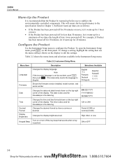
...; -- This time is also used for 20 minutes. Configure the Product Use the Instrument Setup menu to English. Table 2-2. Shows the firmware version installed, model number, and serial number Date Changes the date and date format shown on the top-right corner of the display. For example, if Product has been turned off for 10 minutes, let it was powered off. Table 2-2 shows the...
...; -- This time is also used for 20 minutes. Configure the Product Use the Instrument Setup menu to English. Table 2-2. Shows the firmware version installed, model number, and serial number Date Changes the date and date format shown on the top-right corner of the display. For example, if Product has been turned off for 10 minutes, let it was powered off. Table 2-2 shows the...
Product Manual
Page 37
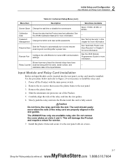
... main power switch. 2. See "Set Up Security" in the slot guides. See the 2638A Calibration Manual for more information. See the 2638 Remote Programmers Guide for service. 7. Install the plastic frame and secure it to the rear panel. 3. Use the ...turn on slots 2 and 3. Slowly push the relay card into the Product until the card is fully seated. WCaution Do not force the relay card into the slot. 2 Initial Setup and Configuration Input Module and Relay Card Installation Table 2-2. Configure the LAN Ethernet or serial USB communication Remote Port settings...
... main power switch. 2. See "Set Up Security" in the slot guides. See the 2638A Calibration Manual for more information. See the 2638 Remote Programmers Guide for service. 7. Install the plastic frame and secure it to the rear panel. 3. Use the ...turn on slots 2 and 3. Slowly push the relay card into the Product until the card is fully seated. WCaution Do not force the relay card into the slot. 2 Initial Setup and Configuration Input Module and Relay Card Installation Table 2-2. Configure the LAN Ethernet or serial USB communication Remote Port settings...

Product Manual
Page 46
... turn . 4. Power on the Product with the main power switch. 2. Configure the channel. 2638A Users Manual Input Wiring Instructions Use the procedure below and refer to Figure 3-1 for instructions on how to wire a 2-wire, 3-wire, or 4-wire input to green and shows all channels available on the left side of the Channel Setup menu as shown in Figure 3-3. If the Input Module is recognized, the module indicator changes...
... turn . 4. Power on the Product with the main power switch. 2. Configure the channel. 2638A Users Manual Input Wiring Instructions Use the procedure below and refer to Figure 3-1 for instructions on how to wire a 2-wire, 3-wire, or 4-wire input to green and shows all channels available on the left side of the Channel Setup menu as shown in Figure 3-3. If the Input Module is recognized, the module indicator changes...
Product Manual
Page 64
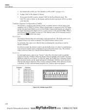
... the data file. The default totalizer mode is set in the Scan menu. Without a filter the Product detects multiple closures that results in the Scan/Monitor menu. When a digital input is connected to the TOT input on one closure. 2638A Users Manual 3. To measure the DIO, monitor channel Ch401 in multiple signals on the rear panel and Ch402 is read /reset...
... the data file. The default totalizer mode is set in the Scan menu. Without a filter the Product detects multiple closures that results in the Scan/Monitor menu. When a digital input is connected to the TOT input on one closure. 2638A Users Manual 3. To measure the DIO, monitor channel Ch401 in multiple signals on the rear panel and Ch402 is read /reset...

Product Manual
Page 79
Like Interval, the user manually sets the number of 0 is set the scan to happen only when the user manually pushes the Scan/Monitor key on the Digital I/O port detects a low condition. This trigger type lets the user set TRIG input on the front panel. 2638A Users Manual Figure 4-3. Test Setup Menu Example hcn032.eps Trigger Type The Trigger Type tells the Product when and how to scan (Scan Count) when the key is...
Like Interval, the user manually sets the number of 0 is set the scan to happen only when the user manually pushes the Scan/Monitor key on the Digital I/O port detects a low condition. This trigger type lets the user set TRIG input on the front panel. 2638A Users Manual Figure 4-3. Test Setup Menu Example hcn032.eps Trigger Type The Trigger Type tells the Product when and how to scan (Scan Count) when the key is...

Product Manual
Page 83
Set all channels to be scanned to highlight Resume Scan then . 3. Once the low condition is triggered by the interval configuration. 2638A Users Manual Automatic Power Loss Scan Resume In the event that it can be accessed. 1. Configure the Test Setup. See "Configure a Scan" on this feature: 1. The ... and wait for next external trigger. 4-10 MyFlukeStore Shop for Fluke products online at: www. .com 1.888.610.7664 The scan is detected, the scan sweep starts and runs as directed by a low condition in the rear-panel Trig input. To turn on page 4-5. 2. At any...
Set all channels to be scanned to highlight Resume Scan then . 3. Once the low condition is triggered by the interval configuration. 2638A Users Manual Automatic Power Loss Scan Resume In the event that it can be accessed. 1. Configure the Test Setup. See "Configure a Scan" on this feature: 1. The ... and wait for next external trigger. 4-10 MyFlukeStore Shop for Fluke products online at: www. .com 1.888.610.7664 The scan is detected, the scan sweep starts and runs as directed by a low condition in the rear-panel Trig input. To turn on page 4-5. 2. At any...

Product Manual
Page 102
... the same rating, voltage, and type. Solution 3: Contact Fluke Calibration. Cause 1: Input Module not fully seated. Cause 3: Input Module has failed. 7 Error Messages and Troubleshooting Troubleshooting Troubleshooting In the event that supplies power to the Product is not properly set. Always replace the fuse with the AC mains power supply rate. Cause 2: AC mains power. Solution 2: Press any front panel key to understand and solve the problem. Cause...
... the same rating, voltage, and type. Solution 3: Contact Fluke Calibration. Cause 1: Input Module not fully seated. Cause 3: Input Module has failed. 7 Error Messages and Troubleshooting Troubleshooting Troubleshooting In the event that supplies power to the Product is not properly set. Always replace the fuse with the AC mains power supply rate. Cause 2: AC mains power. Solution 2: Press any front panel key to understand and solve the problem. Cause...

Product Manual
Page 103
... the trigger type in less than 30 seconds. Troubleshooting Chart (cont.) Causes and Solutions Cause 1: USB drive not installed properly. Cause: The internal memory or USB drive is fully inserted. Solution 1: Make sure the USB drive is out of memory. Cause 1: The Auto Recording feature is started. Solution: Delete or transfer some files to be triggered. 2638A Users Manual Problem Cannot read USB drive...
... the trigger type in less than 30 seconds. Troubleshooting Chart (cont.) Causes and Solutions Cause 1: USB drive not installed properly. Cause: The internal memory or USB drive is fully inserted. Solution 1: Make sure the USB drive is out of memory. Cause 1: The Auto Recording feature is started. Solution: Delete or transfer some files to be triggered. 2638A Users Manual Problem Cannot read USB drive...


