
Fluke 73, 77, 175, 177, and 179 Digital Multimeter Datasheet
Page 1
...leads, 9 V battery (installed), and manual. Ordering information Fluke-175 Digital Multimeter Fluke-177 Digital Multimeter Fluke-179 Digital Multimeter Fluke-73-3 Digital Multimeter Fluke-77-3 Digital Multimeter Fluke-179/61 Combo Kit Fluke-179/1AC Electricians Combo Kit Fluke-179/EDA Combo Kit Fluke-179/TPK Combo Kit For more measurement...TL220 See page 39 C25 See page 44 80T-IR See page 42 80I-400 See page 40 Fluke 73 Included accessories Every Fluke 170 Series meter comes packaged with the optional TPAK magnetic hanger Electrical safety All inputs are specified from 5 % ...
...leads, 9 V battery (installed), and manual. Ordering information Fluke-175 Digital Multimeter Fluke-177 Digital Multimeter Fluke-179 Digital Multimeter Fluke-73-3 Digital Multimeter Fluke-77-3 Digital Multimeter Fluke-179/61 Combo Kit Fluke-179/1AC Electricians Combo Kit Fluke-179/EDA Combo Kit Fluke-179/TPK Combo Kit For more measurement...TL220 See page 39 C25 See page 44 80T-IR See page 42 80I-400 See page 40 Fluke 73 Included accessories Every Fluke 170 Series meter comes packaged with the optional TPAK magnetic hanger Electrical safety All inputs are specified from 5 % ...

FE 175,177,179 Users Manual
Page 3
Table of Contents Title Page Contacting Fluke ...1 "Warning" and "Caution" Statements 1 Unsafe Voltage...1 Test Lead Alert ...1 Battery Saver ("Sleep Mode 2 Terminals ...2 Rotary Switch Positions...2 Display ...3 MIN MAX AVG Recording Mode 4 Display HOLD and AutoHOLD Modes 4 YELLOW Button ...4 Display Backlight (Model 177 and 179 Only 4 Manual Ranging and Autoranging 5 Power-Up Options ...5 Making Basic Measurements...
Table of Contents Title Page Contacting Fluke ...1 "Warning" and "Caution" Statements 1 Unsafe Voltage...1 Test Lead Alert ...1 Battery Saver ("Sleep Mode 2 Terminals ...2 Rotary Switch Positions...2 Display ...3 MIN MAX AVG Recording Mode 4 Display HOLD and AutoHOLD Modes 4 YELLOW Button ...4 Display Backlight (Model 177 and 179 Only 4 Manual Ranging and Autoranging 5 Power-Up Options ...5 Making Basic Measurements...
FE 175,177,179 Users Manual
Page 4
... fingers behind the finger guards. ⇒ Remove test leads from the Meter before testing resistance, continuity, diodes, or capacitance. ⇒ Do not use the Meter or test leads if they appear damaged, or if the Meter is not operating properly. Meter in this manual or the protection provided by TÜV (Technischer Überwachungs Verein) Product...
... fingers behind the finger guards. ⇒ Remove test leads from the Meter before testing resistance, continuity, diodes, or capacitance. ⇒ Do not use the Meter or test leads if they appear damaged, or if the Meter is not operating properly. Meter in this manual or the protection provided by TÜV (Technischer Überwachungs Verein) Product...

FE 175,177,179 Users Manual
Page 5
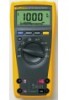
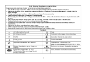
... manual applies to check that could cause bodily harm or death. All figures show the Model 179. These meters meet CAT III and CAT IV IEC 61010 standards. CAT III meters are in the world Visit Fluke's web site at: www.fluke.com Register your Meter ... measurement with a 6000-count, 3 3/4-digit display and a bar graph. CAT IV meters are batterypowered, true-RMS multimeters (hereafter "the Meter") with a test lead in fixed-equipment installations at : register.fluke.com Models 175, 177 & 179 True RMS Multimeters "Warning" and "Caution" Statements A " XWWarning" identifies ...
... manual applies to check that could cause bodily harm or death. All figures show the Model 179. These meters meet CAT III and CAT IV IEC 61010 standards. CAT III meters are in the world Visit Fluke's web site at: www.fluke.com Register your Meter ... measurement with a 6000-count, 3 3/4-digit display and a bar graph. CAT IV meters are batterypowered, true-RMS multimeters (hereafter "the Meter") with a test lead in fixed-equipment installations at : register.fluke.com Models 175, 177 & 179 True RMS Multimeters "Warning" and "Caution" Statements A " XWWarning" identifies ...

FE 175,177,179 Users Manual
Page 6
... for 2 minutes maximum). Hz Frequency of AC A 2 Hz to 99.99 kHz. To disable the Sleep mode, hold down the YELLOW button while turning the Meter on at 250 Ω. L DC voltage 1 mV to 1 kHz. F AC A from 2 Hz to 30 kHz. Note: AC voltage and current AC-coupled, ...− 40 °F to + 752 °F e Ohms from 30.0 mV to 600 mV. The Sleep mode is displayed. Models 175, 177 & 179 Users Manual Battery Saver ("Sleep Mode") The Meter enters the "Sleep mode" and blanks the display if there is no function change or button press for 2 minutes maximum) and frequency...
... for 2 minutes maximum). Hz Frequency of AC A 2 Hz to 99.99 kHz. To disable the Sleep mode, hold down the YELLOW button while turning the Meter on at 250 Ω. L DC voltage 1 mV to 1 kHz. F AC A from 2 Hz to 30 kHz. Note: AC voltage and current AC-coupled, ...− 40 °F to + 752 °F e Ohms from 30.0 mV to 600 mV. The Sleep mode is displayed. Models 175, 177 & 179 Users Manual Battery Saver ("Sleep Mode") The Meter enters the "Sleep mode" and blanks the display if there is no function change or button press for 2 minutes maximum) and frequency...

FE 175,177,179 Users Manual
Page 7
...Negative readings. Then the Meter beeps and displays new reading. bAtt diSC EEPr Err CAL Err Error Messages Replace the battery immediately. Calibrate Meter. 3 Display holds present reading until it detects new stable input. Manual Range The user selects the range. 13 ± Bar graph polarity. ...14 0L 15 LEAd WThe input out of range. Have Meter serviced. Displayed when the rotary ...
...Negative readings. Then the Meter beeps and displays new reading. bAtt diSC EEPr Err CAL Err Error Messages Replace the battery immediately. Calibrate Meter. 3 Display holds present reading until it detects new stable input. Manual Range The user selects the range. 13 ± Bar graph polarity. ...14 0L 15 LEAd WThe input out of range. Have Meter serviced. Displayed when the rotary ...

FE 175,177,179 Users Manual
Page 8
...will not be captured. To resume normal operation at any time, press HOLD for 1 second or turn the rotary switch. Models 175, 177 & 179 Users Manual MIN MAX AVG Recording Mode The MIN MAX AVG recording mode captures the minimum and maximum input values, and calculates a running average of ... HOLD again to activate Display HOLD. To pause MIN MAX AVG recording without erasing stored values, press HOLD. hAh In the AutoHOLD mode, the Meter holds the reading on a rotary switch setting, e.g., to step through the low (MIN), average (AVG), and present readings. In the Display HOLD mode...
...will not be captured. To resume normal operation at any time, press HOLD for 1 second or turn the rotary switch. Models 175, 177 & 179 Users Manual MIN MAX AVG Recording Mode The MIN MAX AVG recording mode captures the minimum and maximum input values, and calculates a running average of ... HOLD again to activate Display HOLD. To pause MIN MAX AVG recording without erasing stored values, press HOLD. hAh In the AutoHOLD mode, the Meter holds the reading on a rotary switch setting, e.g., to step through the low (MIN), average (AVG), and present readings. In the Display HOLD mode...

FE 175,177,179 Users Manual
Page 9
... or turn off display; Manual Ranging and Autoranging Power-Up Options To select a Power-Up Option, hold down ("Sleep mode"). the software version number is displayed. Dampens display fluctuations of rapidly changing inputs by digital filtering. S Disables automatic 2-minute backlight timeout. (Model 177 and 179 Only) 5 The Meter returns to Autorange and Auto...
... or turn off display; Manual Ranging and Autoranging Power-Up Options To select a Power-Up Option, hold down ("Sleep mode"). the software version number is displayed. Dampens display fluctuations of rapidly changing inputs by digital filtering. S Disables automatic 2-minute backlight timeout. (Model 177 and 179 Only) 5 The Meter returns to Autorange and Auto...

FE 175,177,179 Users Manual
Page 10
Warning To avoid electric shock, injury, or damage to the Meter, disconnect circuit power and discharge all high-voltage capacitors before connecting the live lead before XW removing the common test lead. Measuring AC and DC ... HOLD MIN MAX RANGE Measuring Resistance HOLD MIN MAX RANGE Measuring Capacitance HOLD MIN MAX RANGE + _ + _ AIK03F.EPS + _ + 6 AIK04F.EPS AIK05F.EPS Models 175, 177 & 179 Users Manual Making Basic Measurements The figures on the following pages show how to the circuit or device, connect the common (COM) test lead before testing...
Warning To avoid electric shock, injury, or damage to the Meter, disconnect circuit power and discharge all high-voltage capacitors before connecting the live lead before XW removing the common test lead. Measuring AC and DC ... HOLD MIN MAX RANGE Measuring Resistance HOLD MIN MAX RANGE Measuring Capacitance HOLD MIN MAX RANGE + _ + _ AIK03F.EPS + _ + 6 AIK04F.EPS AIK05F.EPS Models 175, 177 & 179 Users Manual Making Basic Measurements The figures on the following pages show how to the circuit or device, connect the common (COM) test lead before testing...

FE 175,177,179 Users Manual
Page 12
... are : • AC voltage: below 5% of 600 mV AC, or 30 mV AC • AC current: below 5% of range. Unspecified input levels on a True RMS meter when the test leads are open -circuit potential to earth is why AC voltage and current ranges are plugged into the current terminals. Non-zero... digits that are displayed on the lowest ranges are normal. Models 175, 177 & 179 Users Manual XW Measuring AC or DC Current Warning To avoid personal injury or damage to the...
... are : • AC voltage: below 5% of 600 mV AC, or 30 mV AC • AC current: below 5% of range. Unspecified input levels on a True RMS meter when the test leads are open -circuit potential to earth is why AC voltage and current ranges are plugged into the current terminals. Non-zero... digits that are displayed on the lowest ranges are normal. Models 175, 177 & 179 Users Manual XW Measuring AC or DC Current Warning To avoid personal injury or damage to the...

FE 175,177,179 Users Manual
Page 13
...45, and 60 V. The trigger level is useful for making peak and null adjustments and for example (see below), the major divisions on an analog Meter. AIK09F.EPS ⇒ To exit frequency, press YELLOW button or turn the rotary switch. ⇒ In frequency, the bar graph shows the AC/... or AC current accurately up to the left. It has an overload indicator ( ) to the right and a polarity indicator (±) to 1 kHz. ⇒ Select progressively lower ranges using manual ranging for a stable reading. Because the bar graph updates about 40 times per second, which is 10 times faster than the...
...45, and 60 V. The trigger level is useful for making peak and null adjustments and for example (see below), the major divisions on an analog Meter. AIK09F.EPS ⇒ To exit frequency, press YELLOW button or turn the rotary switch. ⇒ In frequency, the bar graph shows the AC/... or AC current accurately up to the left. It has an overload indicator ( ) to the right and a polarity indicator (±) to 1 kHz. ⇒ Select progressively lower ranges using manual ranging for a stable reading. Because the bar graph updates about 40 times per second, which is 10 times faster than the...

FE 175,177,179 Users Manual
Page 14
Models 175, 177 & 179 Users Manual Cleaning Wipe the case with a damp cloth and mild detergent. XW Testing the Fuses Warning To avoid electrical shock or injury, remove the test leads and any input signals before replacing the fuse. Test fuses as shown below. Do not use abrasives or solvents. Dirt or moisture in the terminals can affect readings. HOLD MINMAX RANGE 440 mA 11 A
Models 175, 177 & 179 Users Manual Cleaning Wipe the case with a damp cloth and mild detergent. XW Testing the Fuses Warning To avoid electrical shock or injury, remove the test leads and any input signals before replacing the fuse. Test fuses as shown below. Do not use abrasives or solvents. Dirt or moisture in the terminals can affect readings. HOLD MINMAX RANGE 440 mA 11 A

FE 175,177,179 Users Manual
Page 16
...1.2 % + 2 1.2 % + 2 10 % typical 1.5 % + 3 1.2 % + 2 1.2 % + 2 1.2 % + 2 10 % typical 1.5 % + 3 12 Models 175, 177 & 179 Users Manual Function Range 1 Resolution Accuracy ± ( [ % of Reading ] + [ Counts ] ) Model 175 Model 177 Model 179 AC Volts 2,3 600.0 mV 6.000 V 60.00 V 600.0 V 1000 V 0.1 mV 0.001 V 0.01 V 0.1 V 1 V 1.0 % + 3 (45 Hz to 500 ...MΩ 1 Ω 0.1 Ω 0.001 kΩ 0.01 kΩ 0.1 kΩ 0.001 MΩ 0.01 MΩ Meter beeps at < 25 Ω, beeper turns off at 1000 V. 3. Crest factor of ≤ 3 at full scale up to 100 % of range. 2.
...1.2 % + 2 1.2 % + 2 10 % typical 1.5 % + 3 1.2 % + 2 1.2 % + 2 1.2 % + 2 10 % typical 1.5 % + 3 12 Models 175, 177 & 179 Users Manual Function Range 1 Resolution Accuracy ± ( [ % of Reading ] + [ Counts ] ) Model 175 Model 177 Model 179 AC Volts 2,3 600.0 mV 6.000 V 60.00 V 600.0 V 1000 V 0.1 mV 0.001 V 0.01 V 0.1 V 1 V 1.0 % + 3 (45 Hz to 500 ...MΩ 1 Ω 0.1 Ω 0.001 kΩ 0.01 kΩ 0.1 kΩ 0.001 MΩ 0.01 MΩ Meter beeps at < 25 Ω, beeper turns off at 1000 V. 3. Crest factor of ≤ 3 at full scale up to 100 % of range. 2.


