Fluke 1520 MegOhmMeter Datasheet
Page 2
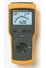
... storage • Four C-cell alkaline batteries, installed • Instruction manual • Instruction manual on recycled paper. eAlrlgriygh.ctsoremserved. Printed in U.S.A. 6/2000 1273840 D-ENG-N Rev A Printed on CD-ROM Optional Accessories • SH 100 Shoulder Strap • TPAK Strap and Magnet for hanging the Fluke 1520 Optional TPAK Meter Strap and Magnet Hanging Kit Optional...
... storage • Four C-cell alkaline batteries, installed • Instruction manual • Instruction manual on recycled paper. eAlrlgriygh.ctsoremserved. Printed in U.S.A. 6/2000 1273840 D-ENG-N Rev A Printed on CD-ROM Optional Accessories • SH 100 Shoulder Strap • TPAK Strap and Magnet for hanging the Fluke 1520 Optional TPAK Meter Strap and Magnet Hanging Kit Optional...

FE 1520 Users Manual
Page 1
Printed in USA All product names are trademarks of their respective companies. All rights reserved. ® 1520 MegOhmMeter Users Manual September 2000 Rev.2, 2/03 © 2000-2003 Fluke Corporation.
Printed in USA All product names are trademarks of their respective companies. All rights reserved. ® 1520 MegOhmMeter Users Manual September 2000 Rev.2, 2/03 © 2000-2003 Fluke Corporation.

FE 1520 Users Manual
Page 8
... Symbols A Caution identifies conditions and actions that pose hazard(s) to the level of OVERVOLTAGE CATEGORY ,,, is equipment in the manual are explained below. International symbols on the Meter and in fixed installations (e.g., electricity meter and primary over-current protection equipment.... 3 Y Risk of electric shock J Earth W See manual I Fuse T Equipment protected by double or reinforced Insulation D AC or DC M Battery Recycling information P CAT III Conforms to CSA...
... Symbols A Caution identifies conditions and actions that pose hazard(s) to the level of OVERVOLTAGE CATEGORY ,,, is equipment in the manual are explained below. International symbols on the Meter and in fixed installations (e.g., electricity meter and primary over-current protection equipment.... 3 Y Risk of electric shock J Earth W See manual I Fuse T Equipment protected by double or reinforced Insulation D AC or DC M Battery Recycling information P CAT III Conforms to CSA...
FE 1520 Users Manual
Page 9
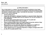
... carefully before using the probes, keep your fingers behind the finger guards on the probes. • Measurements can be replaced. Check test lead continuity. Fluke 1520 Users Manual W Safety Information Use of additional operating circuits connected in a manner not specified by the manufacturer may impair safety features/protection provided by transient currents. •...
... carefully before using the probes, keep your fingers behind the finger guards on the probes. • Measurements can be replaced. Check test lead continuity. Fluke 1520 Users Manual W Safety Information Use of additional operating circuits connected in a manner not specified by the manufacturer may impair safety features/protection provided by transient currents. •...

FE 1520 Users Manual
Page 11
... Low Resistance function. Key and Switch Descriptions T L Rotary switch To select a measurement function. Press and hold TEST, then press LOCK and simultaneously release both buttons. Fluke 1520 Users Manual Key functions Table 1. To unlock: press LOCK or TEST again. 6 The icon V LOCK appears on the display. • Insulation Resistance- Used for the Insulation...
... Low Resistance function. Key and Switch Descriptions T L Rotary switch To select a measurement function. Press and hold TEST, then press LOCK and simultaneously release both buttons. Fluke 1520 Users Manual Key functions Table 1. To unlock: press LOCK or TEST again. 6 The icon V LOCK appears on the display. • Insulation Resistance- Used for the Insulation...
FE 1520 Users Manual
Page 13
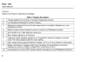
... the last measurement in Insulation Resistance or Low Resistance function. 4 Beeper symbol shows if beeper function is present on in Insulation or Low Resistance functions. 8 Fluke 1520 Users Manual Display Table 2 and Figure 2 describe the display.
... the last measurement in Insulation Resistance or Low Resistance function. 4 Beeper symbol shows if beeper function is present on in Insulation or Low Resistance functions. 8 Fluke 1520 Users Manual Display Table 2 and Figure 2 describe the display.
FE 1520 Users Manual
Page 15
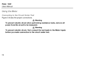
Fluke 1520 Users Manual Using the Meter Connecting to be measured. Warning To prevent electric shock when performing resistance tests, remove all W power from the circuit to the Circuit Under Test W Figure 3 shows the proper connections. Warning To prevent electric shock, first connect the test leads to the Meter inputs before you make connection to the circuit under test. 10
Fluke 1520 Users Manual Using the Meter Connecting to be measured. Warning To prevent electric shock when performing resistance tests, remove all W power from the circuit to the Circuit Under Test W Figure 3 shows the proper connections. Warning To prevent electric shock, first connect the test leads to the Meter inputs before you make connection to the circuit under test. 10
FE 1520 Users Manual
Page 17
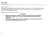
W Measuring Insulation Resistance Warning • Measuring insulation resistance requires the application of potentially dangerous voltages to the desired function. In Lo Ohms mode, the meter turns off after 5 minutes of non-use . To turn the meter back on, turn the rotary switch to OFF, then to the circuit. Fluke 1520 Users Manual Auto-Shut-Off The Meter automatically turns off after 15 minutes of non-use . This may include exposed bonded metalwork. • Before proceeding, ensure that the installation is correctly wired and no personnel are endangered by any tests. 12
W Measuring Insulation Resistance Warning • Measuring insulation resistance requires the application of potentially dangerous voltages to the desired function. In Lo Ohms mode, the meter turns off after 5 minutes of non-use . To turn the meter back on, turn the rotary switch to OFF, then to the circuit. Fluke 1520 Users Manual Auto-Shut-Off The Meter automatically turns off after 15 minutes of non-use . This may include exposed bonded metalwork. • Before proceeding, ensure that the installation is correctly wired and no personnel are endangered by any tests. 12
FE 1520 Users Manual
Page 19
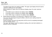
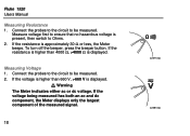
..., while the main reading shows the decreasing voltage. When resistance is higher than the maximum display range, the meter reacts as the main display. Fluke 1520 Users Manual The Meter beeps when the reading is selected. 14 The upper right display holds the resistance reading until the circuit is selected, the display reads...
..., while the main reading shows the decreasing voltage. When resistance is higher than the maximum display range, the meter reacts as the main display. Fluke 1520 Users Manual The Meter beeps when the reading is selected. 14 The upper right display holds the resistance reading until the circuit is selected, the display reads...
FE 1520 Users Manual
Page 21
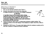
... probes, the voltage is > 30 V ac or dc, remove the voltage from the circuit under test before proceeding with the next step. acf06f.eps 3. Fluke 1520 Users Manual Measuring Low Resistance To measure low resistance: 1. Connect the probes to the circuit to be measured. W If voltage is present on the main display. If...
... probes, the voltage is > 30 V ac or dc, remove the voltage from the circuit under test before proceeding with the next step. acf06f.eps 3. Fluke 1520 Users Manual Measuring Low Resistance To measure low resistance: 1. Connect the probes to the circuit to be measured. W If voltage is present on the main display. If...
FE 1520 Users Manual
Page 23
... the resistance is higher than 660 V, >660 V is approximately 30 Ω or less, the Meter beeps. Connect the probes to the circuit to be measured. Fluke 1520 Users Manual Measuring Resistance 1.
... the resistance is higher than 660 V, >660 V is approximately 30 Ω or less, the Meter beeps. Connect the probes to the circuit to be measured. Fluke 1520 Users Manual Measuring Resistance 1.

FE 1520 Users Manual
Page 25
Fluke 1520 Users Manual Maintaining the Meter This section provides basic maintenance information, including fuse and battery replacement instructions. Remove any residue afterwards. Do not use abrasives or solvents. 20 Periodically wipe the case with soap and water. Cleaning Clean only with a damp cloth and mild detergent. Caution Do not attempt to repair or service your Meter unless you are qualified to do so and have the relevant calibration, performance test, and service information.
Fluke 1520 Users Manual Maintaining the Meter This section provides basic maintenance information, including fuse and battery replacement instructions. Remove any residue afterwards. Do not use abrasives or solvents. 20 Periodically wipe the case with soap and water. Cleaning Clean only with a damp cloth and mild detergent. Caution Do not attempt to repair or service your Meter unless you are qualified to do so and have the relevant calibration, performance test, and service information.
FE 1520 Users Manual
Page 27
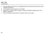
Replace the C cells as shown in the battery compartment. 7. Observe the battery polarity shown in Figure 5. Secure the battery access lid back in position with a flat-blade screwdriver. 5. Fluke 1520 Users Manual 4. Lift the battery access lid away from the Meter. 6. Place the Meter face down on a nonabrasive surface and loosen the two screws with the two screws. 22
Replace the C cells as shown in the battery compartment. 7. Observe the battery polarity shown in Figure 5. Secure the battery access lid back in position with a flat-blade screwdriver. 5. Fluke 1520 Users Manual 4. Lift the battery access lid away from the Meter. 6. Place the Meter face down on a nonabrasive surface and loosen the two screws with the two screws. 22
FE 1520 Users Manual
Page 29
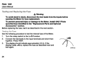
Fluke 1520 Users Manual W Testing and Replacing the Fuse Warning To avoid electric shock, disconnect the test leads from the inputs before opening the Meter for fuse replacement. Before ... display should indicate approximately 0.5 Ω. Testing the Fuse e Use the following procedure to the Lo Function. 2. Connect the test leads to the Meter, install ONLY Fluke specified fuse identified in the next section. Press TEST. 3. acf06f.eps 24 To prevent personal injury or damage to the input terminals and short them...
Fluke 1520 Users Manual W Testing and Replacing the Fuse Warning To avoid electric shock, disconnect the test leads from the inputs before opening the Meter for fuse replacement. Before ... display should indicate approximately 0.5 Ω. Testing the Fuse e Use the following procedure to the Lo Function. 2. Connect the test leads to the Meter, install ONLY Fluke specified fuse identified in the next section. Press TEST. 3. acf06f.eps 24 To prevent personal injury or damage to the input terminals and short them...
FE 1520 Users Manual
Page 31
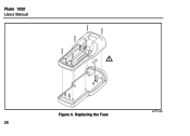
Replacing the Fuse acf11f.eps 26 Fluke 1520 Users Manual Figure 6.
Replacing the Fuse acf11f.eps 26 Fluke 1520 Users Manual Figure 6.
FE 1520 Users Manual
Page 33
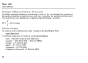
... Centers To locate an authorized service center, visit us on the World Wide Web: www.fluke.com or call Fluke using any of the phone numbers listed below: USA: 1-888-99-FLUKE (1-888-993-5853) Canada: 1-800-36-FLUKE (1-800-363-5853) Europe: +31 402-678-200 Japan: +81-3-3434-0181 Singapore: +65-738... the circuit, and then calculating the resistance of Measurement for Resistance The Meter measures resistance by inducing a current in the world: +1-425-446-5500 28 Fluke 1520 Users Manual Principle of the circuit.
... Centers To locate an authorized service center, visit us on the World Wide Web: www.fluke.com or call Fluke using any of the phone numbers listed below: USA: 1-888-99-FLUKE (1-888-993-5853) Canada: 1-800-36-FLUKE (1-800-363-5853) Europe: +31 402-678-200 Japan: +81-3-3434-0181 Singapore: +65-738... the circuit, and then calculating the resistance of Measurement for Resistance The Meter measures resistance by inducing a current in the world: +1-425-446-5500 28 Fluke 1520 Users Manual Principle of the circuit.

FE 1520 Users Manual
Page 35
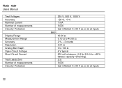
Fluke 1520 Users Manual Size Weight Drop requirement Shock and Vibration Electrical Safety Maximum Operating Voltage Protection Levels Immunity & Emmissions ESD Mechanical Specifications 23,4 x 10 x 6,4 cm (9.2 x 3.9 x 2.5 in) 1 kg (2.2 lbs.) ...
Fluke 1520 Users Manual Size Weight Drop requirement Shock and Vibration Electrical Safety Maximum Operating Voltage Protection Levels Immunity & Emmissions ESD Mechanical Specifications 23,4 x 10 x 6,4 cm (9.2 x 3.9 x 2.5 in) 1 kg (2.2 lbs.) ...
FE 1520 Users Manual
Page 37
Fluke 1520 Users Manual Test Voltages Accuracy Nominal Current Number of measurements Circuitry Protection Display Range Measurement Range Accuracy Resolution Analog Bar Graph Open Circuit Voltage Short Circuit Current ...
Fluke 1520 Users Manual Test Voltages Accuracy Nominal Current Number of measurements Circuitry Protection Display Range Measurement Range Accuracy Resolution Analog Bar Graph Open Circuit Voltage Short Circuit Current ...
FE 1520 Users Manual
Page 39
... is purchased through a Fluke authorized sales outlet or Buyer has paid the applicable international price. Fluke 1520 Users Manual Limited Warranty & Limitation of Liability Each Fluke product is warranted to be returned to 34 Fluke's warranty obligation is limited, at Fluke's option, to refund of...a defective product which , in accordance with a description of operation or handling. Following repair, the product will operate substantially in Fluke's opinion, has been misused, altered, neglected, contaminated, or damaged by use and service. This warranty extends only to the...
... is purchased through a Fluke authorized sales outlet or Buyer has paid the applicable international price. Fluke 1520 Users Manual Limited Warranty & Limitation of Liability Each Fluke product is warranted to be returned to 34 Fluke's warranty obligation is limited, at Fluke's option, to refund of...a defective product which , in accordance with a description of operation or handling. Following repair, the product will operate substantially in Fluke's opinion, has been misused, altered, neglected, contaminated, or damaged by use and service. This warranty extends only to the...

FE 1520 Users Manual
Page 41
Fluke 1520 Users Manual 36
Fluke 1520 Users Manual 36


