Calibration Guide
Page 1
All product names are subject to change without notice. Specifications are trademarks of their respective companies. All rights reserved. 123B/124B/125B Industrial ScopeMeter Calibration Manual May 2016 ©2016 Fluke Corporation.
All product names are subject to change without notice. Specifications are trademarks of their respective companies. All rights reserved. 123B/124B/125B Industrial ScopeMeter Calibration Manual May 2016 ©2016 Fluke Corporation.

Calibration Guide
Page 4
... Foil Removal 44 Display Assembly Removal 44 Maintenance 44 How to Clean 44 Storage 44 Battery Replacement 44 Parts and Accessories 45 ii 123B/124B/125B Calibration Manual Calibration Adjustment 33 Calibration Number and Date 33 Start the Calibration Adjustment 33 Warm Up and Pre-Calibration 34 Final Calibration 34 Delta T Gain...
... Foil Removal 44 Display Assembly Removal 44 Maintenance 44 How to Clean 44 Storage 44 Battery Replacement 44 Parts and Accessories 45 ii 123B/124B/125B Calibration Manual Calibration Adjustment 33 Calibration Number and Date 33 Start the Calibration Adjustment 33 Warm Up and Pre-Calibration 34 Final Calibration 34 Delta T Gain...

Calibration Guide
Page 6
123B/124B/125B Calibration Manual iv
123B/124B/125B Calibration Manual iv

Calibration Guide
Page 8
123B/124B/125B Calibration Manual vi
123B/124B/125B Calibration Manual vi
Calibration Guide
Page 9
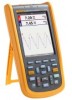
... calibration adjustments. To view, print, or download the latest manual supplement, visit http://us.fluke.com/usen/support/manuals. 1 To register your product, visit http://register.fluke.com. Introduction The 123B/124B/125B ScopeMeter® (the Test Tool or Product) is for the use instrument. This manual provides all the information necessary to -use of the...
... calibration adjustments. To view, print, or download the latest manual supplement, visit http://us.fluke.com/usen/support/manuals. 1 To register your product, visit http://register.fluke.com. Introduction The 123B/124B/125B ScopeMeter® (the Test Tool or Product) is for the use instrument. This manual provides all the information necessary to -use of the...

Calibration Guide
Page 10
... you apply or remove the flexible current probe from hazardous live conductors are damaged. Examine the test leads for cracks or missing plastic. 123B/124B/125B Calibration Manual Safety Information A Warning identifies hazardous conditions and procedures that can cause damage to the Product or the equipment under test. Carefully look at the...
... you apply or remove the flexible current probe from hazardous live conductors are damaged. Examine the test leads for cracks or missing plastic. 123B/124B/125B Calibration Manual Safety Information A Warning identifies hazardous conditions and procedures that can cause damage to the Product or the equipment under test. Carefully look at the...
Calibration Guide
Page 11
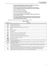
... directives. Conforms to relevant Australian EMC standards. Measurement Category IV is applicable to North American safety standards. Contact your authorized Fluke Service Center for recycling information. Do not dispose of this product is classed as unsorted municipal waste. 3 HAZARDOUS VOLTAGE. Use...and measuring circuits connected at the source of the building's lowvoltage MAINS installation. Symbols used on the Product and in this manual are explained in the WEEE Directive Annex I, this product as category 9 "Monitoring and Control Instrumentation" product. Risk of ...
... directives. Conforms to relevant Australian EMC standards. Measurement Category IV is applicable to North American safety standards. Contact your authorized Fluke Service Center for recycling information. Do not dispose of this product is classed as unsorted municipal waste. 3 HAZARDOUS VOLTAGE. Use...and measuring circuits connected at the source of the building's lowvoltage MAINS installation. Symbols used on the Product and in this manual are explained in the WEEE Directive Annex I, this product as category 9 "Monitoring and Control Instrumentation" product. Risk of ...

Calibration Guide
Page 12
... 4 GS/s Real time sampling 1 μs to 400 Hz Vertical Accuracy 1 % + 0.05 range/div) Max. 123B/124B/125B Calibration Manual Specifications Dual Input Oscilloscope Vertical Frequency Response DC Coupled without probes and test leads (with BB120) 125B, 124B DC to 40 MHz (-3 dB) 123B DC to 20 MHz (-3 dB) with STL120-IV 1:1 shielded test...
... 4 GS/s Real time sampling 1 μs to 400 Hz Vertical Accuracy 1 % + 0.05 range/div) Max. 123B/124B/125B Calibration Manual Specifications Dual Input Oscilloscope Vertical Frequency Response DC Coupled without probes and test leads (with BB120) 125B, 124B DC to 40 MHz (-3 dB) 123B DC to 20 MHz (-3 dB) with STL120-IV 1:1 shielded test...
Calibration Guide
Page 13
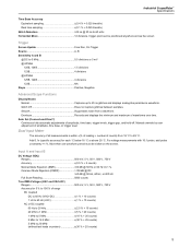
...Run, On Trigger Source A, B Sensitivity A and B @ DC to 5 MHz 0.5 divisions or 5 mV @ 40 MHz 125B, 124B 1.5 divisions 123B 4 divisions @ 60 MHz 125B, 124B 4 divisions 123B NA Slope Positive, Negative Advanced Scope Functions Display Modes Normal Captures up to 25 ns glitches and displays ...analog-like persistence waveform. Smooth Suppresses noise from 18 °C to 28 °C. Manual override by user adjustment of ...
...Run, On Trigger Source A, B Sensitivity A and B @ DC to 5 MHz 0.5 divisions or 5 mV @ 40 MHz 125B, 124B 1.5 divisions 123B 4 divisions @ 60 MHz 125B, 124B 4 divisions 123B NA Slope Positive, Negative Advanced Scope Functions Display Modes Normal Captures up to 25 ns glitches and displays ...analog-like persistence waveform. Smooth Suppresses noise from 18 °C to 28 °C. Manual override by user adjustment of ...

Calibration Guide
Page 14
..., 100 Hz, 1 kHz, 10 kHz, 100 kHz,1 MHz, 10 MHz, and 50 MHz Frequency Range in Continuous Autoset ...........15 Hz (1 Hz) to 50 MHz Accuracy 125B, 124B @ 1 Hz to 1 MHz 0.5 % + 2 counts) @ 1 MHz to 10 MHz 1.0 % + 2 counts) @ 10 MHz to 70 MHz 2.5 % + 2 counts) 123B @ 1 Hz to 1 MHz 0.5 % + 2 counts) @ 1 MHz ... For the total accuracy for AC coupled, add the derating values specified in the table to the table of any signal crest factor. 123B/124B/125B Calibration Manual AC coupled with 1:1 (shielded) test leads 60 Hz (6 Hz with 10:1 probe 1.5 % 50 Hz (5 Hz with 10:1 probe 2 % 33 Hz (3.3 Hz with...
..., 100 Hz, 1 kHz, 10 kHz, 100 kHz,1 MHz, 10 MHz, and 50 MHz Frequency Range in Continuous Autoset ...........15 Hz (1 Hz) to 50 MHz Accuracy 125B, 124B @ 1 Hz to 1 MHz 0.5 % + 2 counts) @ 1 MHz to 10 MHz 1.0 % + 2 counts) @ 10 MHz to 70 MHz 2.5 % + 2 counts) 123B @ 1 Hz to 1 MHz 0.5 % + 2 counts) @ 1 MHz ... For the total accuracy for AC coupled, add the derating values specified in the table to the table of any signal crest factor. 123B/124B/125B Calibration Manual AC coupled with 1:1 (shielded) test leads 60 Hz (6 Hz with 10:1 probe 1.5 % 50 Hz (5 Hz with 10:1 probe 2 % 33 Hz (3.3 Hz with...
Calibration Guide
Page 16
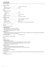
... HOLD) Harmonics values in HOLD) Dual Horizontal Lines High, Low and Peak-Peak Readout Rise or Fall Time Transition Time, 0 %-Level and 100 %-Level Readout (Manual or Auto Leveling; Meter settling time Normal: 2 s @ 1 μs to 10 ms/div. AutoHold (on COM Capacitance (CAP) Ranges 50 nF, 500 nF, 5 &#.... Meter settling time Smooth: 10 s @ 1 μs to 10 ms/div. Beeps when stable. on A) Captures and freezes a stable measurement result. 123B/124B/125B Calibration Manual Continuity (CONT) Beep 30 Ω ±5 Ω) in Single Channel Mode) Accuracy As Oscilloscope Accuracy 8
... HOLD) Harmonics values in HOLD) Dual Horizontal Lines High, Low and Peak-Peak Readout Rise or Fall Time Transition Time, 0 %-Level and 100 %-Level Readout (Manual or Auto Leveling; Meter settling time Normal: 2 s @ 1 μs to 10 ms/div. AutoHold (on COM Capacitance (CAP) Ranges 50 nF, 500 nF, 5 &#.... Meter settling time Smooth: 10 s @ 1 μs to 10 ms/div. Beeps when stable. on A) Captures and freezes a stable measurement result. 123B/124B/125B Calibration Manual Continuity (CONT) Beep 30 Ω ±5 Ω) in Single Channel Mode) Accuracy As Oscilloscope Accuracy 8
Calibration Guide
Page 18
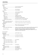
123B/124B/125B Calibration Manual Miscellaneous Display Type 5.7-inch color active matrix TFT Resolution 640 pixels x 480 pixels Waveform Display Vertical 10 div of 40 pixels Horizontal 12 div of ...
123B/124B/125B Calibration Manual Miscellaneous Display Type 5.7-inch color active matrix TFT Resolution 640 pixels x 480 pixels Waveform Display Vertical 10 div of 40 pixels Horizontal 12 div of ...
Calibration Guide
Page 20
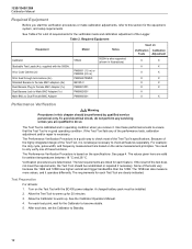
... are qualified to ensure that the Test Tool is calibrated and in good operating condition. The 125B can also measure more values, and it . 123B/124B/125B Calibration Manual Required Equipment Before you receive it operates differently. Verification procedures are based on the specifications. To...all features separately. The Performance Verification Procedure is a quick way to check most of the tests vary because the 124B and 125B have higher vertical and trigger bandwidths than the 123B. Use these functions. The Performance Verification Procedure is based on the same ...
... are qualified to ensure that the Test Tool is calibrated and in good operating condition. The 125B can also measure more values, and it . 123B/124B/125B Calibration Manual Required Equipment Before you receive it operates differently. Verification procedures are based on the specifications. To...all features separately. The Performance Verification Procedure is a quick way to check most of the tests vary because the 124B and 125B have higher vertical and trigger bandwidths than the 123B. Use these functions. The Performance Verification Procedure is based on the same ...
Calibration Guide
Page 21
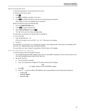
...the BB120 banana to BNC adapter, and a 50 Ω (or lower) BNC termination to turn on Input B. Note toggles between Auto and Manual ranging. Industrial ScopeMeter Performance Verification Input A and Input B Tests To verify a measurement, choose items from a menu: 1. Push . 2. Item...in the menu. 3. Go to select auto ranging (AUTO shows at the top of the Test Tool. toggles between AUTO and MANUAL ranging. Select Factory Default and push . To Turn on Input B if necessary. V). Push . In auto ranging mode, Auto shows...
...the BB120 banana to BNC adapter, and a 50 Ω (or lower) BNC termination to turn on Input B. Note toggles between Auto and Manual ranging. Industrial ScopeMeter Performance Verification Input A and Input B Tests To verify a measurement, choose items from a menu: 1. Push . 2. Item...in the menu. 3. Go to select auto ranging (AUTO shows at the top of the Test Tool. toggles between AUTO and MANUAL ranging. Select Factory Default and push . To Turn on Input B if necessary. V). Push . In auto ranging mode, Auto shows...
Calibration Guide
Page 22
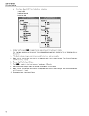
... the time base changes, wait a few seconds for the trace to become stable. 9. The input sensitivity is ±0.025 division (= 1 pixel). 10. Neither AUTO nor MANUAL show on the display. 4. On the Test Tool, push to become stable. 5. Make sure the Input A trace returns to the same position after the... time base between 1 μs/div and 500 ns/div. 8. To set to toggle the time base between 10 ms/div and 5 ms/div. 123B/124B/125B Calibration Manual e. Push to...
... the time base changes, wait a few seconds for the trace to become stable. 9. The input sensitivity is ±0.025 division (= 1 pixel). 10. Neither AUTO nor MANUAL show on the display. 4. On the Test Tool, push to become stable. 5. Make sure the Input A trace returns to the same position after the... time base between 1 μs/div and 500 ns/div. 8. To set to toggle the time base between 10 ms/div and 5 ms/div. 123B/124B/125B Calibration Manual e. Push to...
Calibration Guide
Page 23
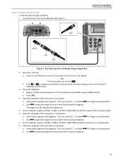
...peak-to Calibrator Scope Output 50 Ω 2. If it is triggered. 15 On the Calibrator, supply a 40 MHz (123B) or 60 MHz (124B/125B) leveled sine wave of the sine wave to -peak (SCOPE output, MODE levsine). If it is not, press to enable ... the signal is well triggered. Verify that the signal is triggered. b. See Figure 3. Push or to change the sensitivity, to select manual sensitivity ranging, and to the Calibrator. b. Input A Trigger Sensitivity Test To test the Input A trigger sensitivity: 1. Connect the Test Tool to lock the ...
...peak-to Calibrator Scope Output 50 Ω 2. If it is triggered. 15 On the Calibrator, supply a 40 MHz (123B) or 60 MHz (124B/125B) leveled sine wave of the sine wave to -peak (SCOPE output, MODE levsine). If it is not, press to enable ... the signal is well triggered. Verify that the signal is triggered. b. See Figure 3. Push or to change the sensitivity, to select manual sensitivity ranging, and to the Calibrator. b. Input A Trigger Sensitivity Test To test the Input A trigger sensitivity: 1. Connect the Test Tool to lock the ...

Calibration Guide
Page 24
... . 4. Table 3. Push . Input A, B Frequency Measurement Accuracy Test Calibrator output, 600 mVpp 1 MHz 10 MHz 40 MHz 60 MHz (124B/125B only) Input A, B Reading 0.993 MHz to 1.007 MHz 09.88 MHz to 10.12 MHz 38.98 MHz to 41.02 MHz 58.48 MHz... Duty Cycle and Pulse Width measurements are not verified separately. 16 Adjust the amplitude of the display). Set up the Calibrator: a. 123B/124B/125B Calibration Manual Input A Frequency Response Upper Transition Point Test To test the Input A frequency response upper transition point: 1. Push to the Calibrator....
... . 4. Table 3. Push . Input A, B Frequency Measurement Accuracy Test Calibrator output, 600 mVpp 1 MHz 10 MHz 40 MHz 60 MHz (124B/125B only) Input A, B Reading 0.993 MHz to 1.007 MHz 09.88 MHz to 10.12 MHz 38.98 MHz to 41.02 MHz 58.48 MHz... Duty Cycle and Pulse Width measurements are not verified separately. 16 Adjust the amplitude of the display). Set up the Calibrator: a. 123B/124B/125B Calibration Manual Input A Frequency Response Upper Transition Point Test To test the Input A frequency response upper transition point: 1. Push to the Calibrator....

Calibration Guide
Page 26
... the sensitivity setting to 6 divisions. 5. Push . f. b. Use and to change the sensitivity setting to manual sensitivity ranging and lock the Input B sensitivity on 200 mV/div. Push to open the SCOPE SETTINGS menu. Note For ...8226; Trigger Input: B • Update: Free Run • Type: Normal • Waveform: Normal 3. Push . 18 123B/124B/125B Calibration Manual Input B Frequency Response Upper Transition Point Test To test the Input B frequency response upper transition point: 1. Note The lower transition point is ≥...
... the sensitivity setting to 6 divisions. 5. Push . f. b. Use and to change the sensitivity setting to manual sensitivity ranging and lock the Input B sensitivity on 200 mV/div. Push to open the SCOPE SETTINGS menu. Note For ...8226; Trigger Input: B • Update: Free Run • Type: Normal • Waveform: Normal 3. Push . 18 123B/124B/125B Calibration Manual Input B Frequency Response Upper Transition Point Test To test the Input B frequency response upper transition point: 1. Note The lower transition point is ≥...

Calibration Guide
Page 28
123B/124B/125B Calibration Manual 2. Turn on the Test Tool: a. Set up the Test Tool: a. b. Push ... the display, push to reset the Test Tool. 9. b. Use to set the trigger level to manual time base ranging and lock the time base on the display. 10. Push . 8. If traces show on 10 ms/...; or to change the time base setting to +1 divisions. c. Push . c. e. Push to manual sensitivity ranging and lock the Input A and Input B sensitivity on the Calibrator is the top of the display. Use ...
123B/124B/125B Calibration Manual 2. Turn on the Test Tool: a. Set up the Test Tool: a. b. Push ... the display, push to reset the Test Tool. 9. b. Use to set the trigger level to manual time base ranging and lock the time base on the display. 10. Push . 8. If traces show on 10 ms/...; or to change the time base setting to +1 divisions. c. Push . c. e. Push to manual sensitivity ranging and lock the Input A and Input B sensitivity on the Calibrator is the top of the display. Use ...

Calibration Guide
Page 30
123B/124B/125B Calibration Manual Input A and Input B DC Voltage Accuracy Test XW Warning To prevent possible electrical shock, fire, or personal injury, make sure that the calibrator is not ... the INPUT SETTINGS A menu. Use to change the time base to the center grid line. 5. Move the Input A and Input B ground level to select manual time base ranging and lock the time base on the calibration source and connecting cables during the following steps. Push . Make these selections: •...
123B/124B/125B Calibration Manual Input A and Input B DC Voltage Accuracy Test XW Warning To prevent possible electrical shock, fire, or personal injury, make sure that the calibrator is not ... the INPUT SETTINGS A menu. Use to change the time base to the center grid line. 5. Move the Input A and Input B ground level to select manual time base ranging and lock the time base on the calibration source and connecting cables during the following steps. Push . Make these selections: •...


