Technical Reference
Page 11
...Printer handling 1-1 1.1.3 Printing 1-1 1.1.4 Software 1-1 1.2 Product Structure 1-2 1.2.1 Printer types 1-2 1.2.2 Standard Parts Included with the Printer 1-2 1.2.3 Related materials for TM...13 1.6.1.1 Printer (TM-U220 1-...EPSON Advanced Printer Driver 2-1 2.1.1.1 General Features of the EPSON Advanced Printer Driver . . 2-1 2.1.1.2 EPSON Advanced Printer Driver Components 2-2 2.1.1.3 EPSON Advanced Printer Driver Support Environment . . . . 2-2 2.1.2 EPSON OPOS ADK 2-3 2.1.2.1 General Features of EPSON OPOS ADK (OPOS Control) . . . 2-3 2.1.2.2 EPSON OPOS ADK Contents 2-4 2.1.2.3 EPSON...
...Printer handling 1-1 1.1.3 Printing 1-1 1.1.4 Software 1-1 1.2 Product Structure 1-2 1.2.1 Printer types 1-2 1.2.2 Standard Parts Included with the Printer 1-2 1.2.3 Related materials for TM...13 1.6.1.1 Printer (TM-U220 1-...EPSON Advanced Printer Driver 2-1 2.1.1.1 General Features of the EPSON Advanced Printer Driver . . 2-1 2.1.1.2 EPSON Advanced Printer Driver Components 2-2 2.1.1.3 EPSON Advanced Printer Driver Support Environment . . . . 2-2 2.1.2 EPSON OPOS ADK 2-3 2.1.2.1 General Features of EPSON OPOS ADK (OPOS Control) . . . 2-3 2.1.2.2 EPSON OPOS ADK Contents 2-4 2.1.2.3 EPSON...
Technical Reference
Page 12
...Paper Near End Detector 3-27 3.4.7 Select Autocutter action 3-28 3.4.8 Connecting the Printer to the Host PC / POS Terminal 3-30 3.4.8.1 Serial Interface model 3-31 3.4.8.2 Parallel Interface Models 3-31 3.4.8.3 USB Interface Models 3-31... 3.4.8.4 Ethernet interface 3-33 3.4.8.5 Connecting a Drawer 3-34 3.5 Install a Printer Driver in the Host PC / POS Terminal 3-34 3.5.1 OPOS 3-34 3.5.1.1 Install and Set up 3-34 3.5.1.2 Package contents of EPSON OPOS ADK 3-37 3.5.2 Advanced Printer...
...Paper Near End Detector 3-27 3.4.7 Select Autocutter action 3-28 3.4.8 Connecting the Printer to the Host PC / POS Terminal 3-30 3.4.8.1 Serial Interface model 3-31 3.4.8.2 Parallel Interface Models 3-31 3.4.8.3 USB Interface Models 3-31... 3.4.8.4 Ethernet interface 3-33 3.4.8.5 Connecting a Drawer 3-34 3.5 Install a Printer Driver in the Host PC / POS Terminal 3-34 3.5.1 OPOS 3-34 3.5.1.1 Install and Set up 3-34 3.5.1.2 Package contents of EPSON OPOS ADK 3-37 3.5.2 Advanced Printer...
Technical Reference
Page 13
... 5-9 5.4.2.4 Printable bitmap format in OPOS 5-9 5.4.3 ESC/POS command 5-9 5.5 Printing for Replacement of the TM-U210/TM-U300 6.1 For Replacement of the TM-U210 6-1 6.1.1 About printing format compatibility 6-1 6.1.1.1 Printing area 6-1 6.1.1.2 Characters 6-2 6.1.1.3 Cutting position from ...statuses 6-5 Rev. Drawer specifications differ, depending on a Line 4-4 4.5 Printer prints "?" or Incorrect Data With Serial Interface 4-7 4.6 Print Speed is Slow When Using Windows Printer Driver 4-7 4.7 Printer doesn't cut roll paper with the autocutter 4-7 4.8 Hexadecimal Dump mode ...
... 5-9 5.4.2.4 Printable bitmap format in OPOS 5-9 5.4.3 ESC/POS command 5-9 5.5 Printing for Replacement of the TM-U210/TM-U300 6.1 For Replacement of the TM-U210 6-1 6.1.1 About printing format compatibility 6-1 6.1.1.1 Printing area 6-1 6.1.1.2 Characters 6-2 6.1.1.3 Cutting position from ...statuses 6-5 Rev. Drawer specifications differ, depending on a Line 4-4 4.5 Printer prints "?" or Incorrect Data With Serial Interface 4-7 4.6 Print Speed is Slow When Using Windows Printer Driver 4-7 4.7 Printer doesn't cut roll paper with the autocutter 4-7 4.8 Hexadecimal Dump mode ...
Technical Reference
Page 19
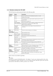
...command This Manual is packed in the carton box. This is required to adjust the setting (Memory Switch) of this printer. If you want to provide power from the TM-U220 to a DM-D, you are customer displays. (Line Display) Consumables Roll Paper This is a utility to get ... has a supplement which is Command Reference Guide of ESC/POS command. PS-180 EPSON power supply unit DM-D105/D205, Direct connection customer display (available only for some DM-D106/DM-D206 serial interface models and some sample programs & Tips. ESC/POS Application Guide This Manual ...
...command This Manual is packed in the carton box. This is required to adjust the setting (Memory Switch) of this printer. If you want to provide power from the TM-U220 to a DM-D, you are customer displays. (Line Display) Consumables Roll Paper This is a utility to get ... has a supplement which is Command Reference Guide of ESC/POS command. PS-180 EPSON power supply unit DM-D105/D205, Direct connection customer display (available only for some DM-D106/DM-D206 serial interface models and some sample programs & Tips. ESC/POS Application Guide This Manual ...
Technical Reference
Page 21
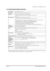
... TM-U220 Technical Reference Guide 1.4 Product Specifications Overview Print method Paper width Cut type Character sets serial impact dot matrix ...voltage 24 VDC ± 7% (optional power supply: EPSON PS-180) Power consumption (except for Japanese model) ...06 lb} *Multilingual means the printer model that can be changed. The type can print any one of the...Two-pass printing font) (JIS X0208-1990): 6879 • Simplified Chinese (Two-pass printing font) (GB18030-2000): 28553 • Traditional Chinese (Two-pass printing font) (Big 5): 13494 • Korean (Two...
... TM-U220 Technical Reference Guide 1.4 Product Specifications Overview Print method Paper width Cut type Character sets serial impact dot matrix ...voltage 24 VDC ± 7% (optional power supply: EPSON PS-180) Power consumption (except for Japanese model) ...06 lb} *Multilingual means the printer model that can be changed. The type can print any one of the...Two-pass printing font) (JIS X0208-1990): 6879 • Simplified Chinese (Two-pass printing font) (GB18030-2000): 28553 • Traditional Chinese (Two-pass printing font) (Big 5): 13494 • Korean (Two...
Technical Reference
Page 22
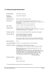
...) *1 This printer adjusts print speed when it prints graphic data, etc. 1-6 General Information Rev. Number of Kanji characters is selectable by control commands. D The spacing of characters: 95 alphanumeric, 48 international characters, Extended graphics: 128 × 12 pages. (15 tables for details. 1.5 Printing and paper Specifications Printing method: Serial impact dot matrix Head wire...
...) *1 This printer adjusts print speed when it prints graphic data, etc. 1-6 General Information Rev. Number of Kanji characters is selectable by control commands. D The spacing of characters: 95 alphanumeric, 48 international characters, Extended graphics: 128 × 12 pages. (15 tables for details. 1.5 Printing and paper Specifications Printing method: Serial impact dot matrix Head wire...
Technical Reference
Page 38
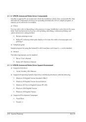
... Sample program for operating automatically. D 2.1.1.2 EPSON Advanced Printer Driver Components Installer recognizes PC environment in which the installation will be done at the same time). Each has functions such as two-color printing, smoothing, continuous printing, and option ...; Driver: User's Manual • Status API: Reference Manual 2.1.1.3 EPSON Advanced Printer Driver Support Environment ❏ Supported interfaces • Serial, Parallel, USB, Ethernet ❏ Supported Operating Systems: Epson has confirmed performance with Visual Basic and Visual C++ can be installed....
... Sample program for operating automatically. D 2.1.1.2 EPSON Advanced Printer Driver Components Installer recognizes PC environment in which the installation will be done at the same time). Each has functions such as two-color printing, smoothing, continuous printing, and option ...; Driver: User's Manual • Status API: Reference Manual 2.1.1.3 EPSON Advanced Printer Driver Support Environment ❏ Supported interfaces • Serial, Parallel, USB, Ethernet ❏ Supported Operating Systems: Epson has confirmed performance with Visual Basic and Visual C++ can be installed....
Technical Reference
Page 41
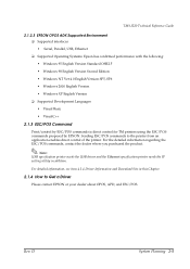
... control of the printer. For detailed information, see item 4.1.4 Driver Information and Download Site in addition. Rev. For the detailed information regarding the ESC/POS commands, contact the dealer where you purchased the product. D System Planning 2-5 TM-U220 Technical Reference Guide 2.1.2.3 EPSON OPOS ADK Supported Environment ❏ Supported interfaces • Serial, Parallel, USB, Ethernet...
... control of the printer. For detailed information, see item 4.1.4 Driver Information and Download Site in addition. Rev. For the detailed information regarding the ESC/POS commands, contact the dealer where you purchased the product. D System Planning 2-5 TM-U220 Technical Reference Guide 2.1.2.3 EPSON OPOS ADK Supported Environment ❏ Supported interfaces • Serial, Parallel, USB, Ethernet...

Technical Reference
Page 42
...: The type of cable that should be used depends on the operation and the handshake method for the TM printer. D 2.2 Connection Form and Cables 2.3 Serial Connection When the TM printer is connected to the host PC with a serial interface, the following sections for the type cable for each connection. 2-6 System Planning Rev. You can operate the...
...: The type of cable that should be used depends on the operation and the handshake method for the TM printer. D 2.2 Connection Form and Cables 2.3 Serial Connection When the TM printer is connected to the host PC with a serial interface, the following sections for the type cable for each connection. 2-6 System Planning Rev. You can operate the...

Technical Reference
Page 43
...type connection, confirm that the DIP switch has been set "Y-type connection: Enable." Type B (*) (*) When RTS/CTS control is connected to TM printer via serial port. 2 1 Application XON/XOFF TM side control (except OPOS) control setting DTR/DSR (DOS, OPOS, Visual C) XON/XOFF 1 Type A or B - 2 DM-D500..."PS-180." Other DM-D: not available DTR/DSR 1 - Type B Type B 2.3.2 Y-connection TM printer is connected to the host PC via serial port and the customer display (DM-D) is used between the TM and DM. RTS/CTS (DOS, Windows driver, Visual C, Visual Basic, MSComm) - On the...
...type connection, confirm that the DIP switch has been set "Y-type connection: Enable." Type B (*) (*) When RTS/CTS control is connected to TM printer via serial port. 2 1 Application XON/XOFF TM side control (except OPOS) control setting DTR/DSR (DOS, OPOS, Visual C) XON/XOFF 1 Type A or B - 2 DM-D500..."PS-180." Other DM-D: not available DTR/DSR 1 - Type B Type B 2.3.2 Y-connection TM printer is connected to the host PC via serial port and the customer display (DM-D) is used between the TM and DM. RTS/CTS (DOS, Windows driver, Visual C, Visual Basic, MSComm) - On the...
Technical Reference
Page 44
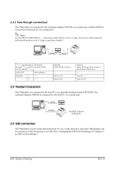
...set to the host PC via a serial port. The customer display (DM-D) is connected to the host PC via a serial port. 2.5 USB connection The TM printer can be connected to the host PC via a USB connector, and other TM printers can be connected to the host PC... System Planning Rev. Type B Type A or B 2.4 Parallel Connection The TM printer is connected to the first printer via a parallel interface board (UB-P02II). D 2.3.3 Pass-through connections The TM printer is connected to the customer display (DM-D) via a serial port, and the DM-D is connected to "Y-type connection: Disable."
...set to the host PC via a serial port. The customer display (DM-D) is connected to the host PC via a serial port. 2.5 USB connection The TM printer can be connected to the host PC via a USB connector, and other TM printers can be connected to the host PC... System Planning Rev. Type B Type A or B 2.4 Parallel Connection The TM printer is connected to the first printer via a parallel interface board (UB-P02II). D 2.3.3 Pass-through connections The TM printer is connected to the customer display (DM-D) via a serial port, and the DM-D is connected to "Y-type connection: Disable."
Technical Reference
Page 48
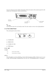
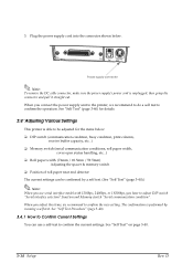
.... You can connect up to four cables to the connector panel (on but not blinking, it means that the printer is shown below . They all connect to the printer. The other interface connector looks slightly different. 3.1.2 The Control Panel The control panel is offline. When this light ...is on the bottom rear of the printer), which is shown below . ❏ POWER LED ❏ ERROR LED ❏ PAPER OUT LED ❏ FEED button 3.1.2.1 LED POWER On:...
.... You can connect up to four cables to the connector panel (on but not blinking, it means that the printer is shown below . They all connect to the printer. The other interface connector looks slightly different. 3.1.2 The Control Panel The control panel is offline. When this light ...is on the bottom rear of the printer), which is shown below . ❏ POWER LED ❏ ERROR LED ❏ PAPER OUT LED ❏ FEED button 3.1.2.1 LED POWER On:...
Technical Reference
Page 51
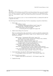
TM-U220 Technical Reference Guide Note: When you use OPOS (OCX driver from EPSON) or the Advanced Printer Driver, you need to) When you use this printer with a serial interface, you have to install drivers. The flow of Roll Paper Near End Detector" (page 3-27)) • Auto cutter ... be installed on page 2-1 and "Install a Printer Driver in Appendix B for how to install the driver. When you need to set them. •DIP switches ("Adjusting the DIP Switches" (page 3-15)) The DIP switches set serial communication conditions, busy condition, print column, receive buffer capacity, ...
TM-U220 Technical Reference Guide Note: When you use OPOS (OCX driver from EPSON) or the Advanced Printer Driver, you need to) When you use this printer with a serial interface, you have to install drivers. The flow of Roll Paper Near End Detector" (page 3-27)) • Auto cutter ... be installed on page 2-1 and "Install a Printer Driver in Appendix B for how to install the driver. When you need to set them. •DIP switches ("Adjusting the DIP Switches" (page 3-15)) The DIP switches set serial communication conditions, busy condition, print column, receive buffer capacity, ...
Technical Reference
Page 60
...connector shown below : ❏ DIP switch (communication condition, busy condition, print column, receive buffer capacity, etc...) ❏ Memory switch (serial communication conditions, roll paper width, cover open status handling, etc...) ❏ Roll paper width (76mm / 69.5mm / 59.5mm) Adjusting ...Serial communication condition". The confirmation is performed by a self test. (See "Self Test" (page 3-40).) Note: When you use a self-test to be adjusted for details. 3.4 Adjusting Various Settings This printer is unplugged; When you connect the power supply unit to the printer...
...connector shown below : ❏ DIP switch (communication condition, busy condition, print column, receive buffer capacity, etc...) ❏ Memory switch (serial communication conditions, roll paper width, cover open status handling, etc...) ❏ Roll paper width (76mm / 69.5mm / 59.5mm) Adjusting ...Serial communication condition". The confirmation is performed by a self test. (See "Self Test" (page 3-40).) Note: When you use a self-test to be adjusted for details. 3.4 Adjusting Various Settings This printer is unplugged; When you connect the power supply unit to the printer...
Technical Reference
Page 61
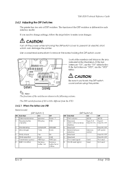
... or Offline (DIP Switch 2) SW Function On 1 Print column 42/35 2 Reserved Type A, B (Auto cutter enable/ Fixed to On disable) 3 Reserved - 4 Serial interface selection Memory switch 5 Reserved - 6 Reserved - 7 Pin 6 reset signal Used 8 Pin 25 reset signal Used Off 40/33 Type D Fixed to Off Fixed...switch Fixed to Off Fixed to Off Not used Not used Rev. Note: The functions of DIP switches. TM-U220 Technical Reference Guide 3.4.2 Adjusting the DIP Switches The printer has two sets of the switches are "STD", use the "US" tables below to make your changes: CAUTION: ...
... or Offline (DIP Switch 2) SW Function On 1 Print column 42/35 2 Reserved Type A, B (Auto cutter enable/ Fixed to On disable) 3 Reserved - 4 Serial interface selection Memory switch 5 Reserved - 6 Reserved - 7 Pin 6 reset signal Used 8 Pin 25 reset signal Used Off 40/33 Type D Fixed to Off Fixed...switch Fixed to Off Fixed to Off Not used Not used Rev. Note: The functions of DIP switches. TM-U220 Technical Reference Guide 3.4.2 Adjusting the DIP Switches The printer has two sets of the switches are "STD", use the "US" tables below to make your changes: CAUTION: ...
Technical Reference
Page 62
See "Notes for "When the letters are US." When you use serial interface model with 1200bps, 2400bps, or 19200bps, you have to Off Not used Note: See the next page for DIP switch 2-1" (page 3-19) about the ... - 8 Pin 31 reset signal Used Off 40/33 Type D Fixed to Off Fixed to adjust DIP switch "Serial interface selection" function and Memory switch "Serial communication condition". 3-16 Setup Rev. Parallel / USB / Ethernet model (Except serial) (DIP Switch 1) SW Function On Off 1 Auto line feed Enabled Disabled 2 Receive buffer capacity 40 bytes 4 KB...
See "Notes for "When the letters are US." When you use serial interface model with 1200bps, 2400bps, or 19200bps, you have to Off Not used Note: See the next page for DIP switch 2-1" (page 3-19) about the ... - 8 Pin 31 reset signal Used Off 40/33 Type D Fixed to Off Fixed to adjust DIP switch "Serial interface selection" function and Memory switch "Serial communication condition". 3-16 Setup Rev. Parallel / USB / Ethernet model (Except serial) (DIP Switch 1) SW Function On Off 1 Auto line feed Enabled Disabled 2 Receive buffer capacity 40 bytes 4 KB...
Technical Reference
Page 63
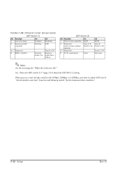
TM-U220 Technical Reference Guide 3.4.2.2 When the letters are US Serial model (DIP Switch 1) SW Function On Off 1 Printing mode Right side up printing mode is a mode used for a printer that is "Right side up Normal printing printing mode mode 2 Receive buffer capacity 40 bytes 4 KB 3 ... Off 40/33 2 Reserved (Auto cutter enable/ disable) 3 Pin 6 reset signal 4 Pin 25 reset signal 5 Reserved 6 Reserved 7 Reserved 8 Serial interface selection Type A, B Type D Fixed to On Fixed to Off Used Used Memory switch Not used Not used Fixed to Off DIP switch Note: When...
TM-U220 Technical Reference Guide 3.4.2.2 When the letters are US Serial model (DIP Switch 1) SW Function On Off 1 Printing mode Right side up printing mode is a mode used for a printer that is "Right side up Normal printing printing mode mode 2 Receive buffer capacity 40 bytes 4 KB 3 ... Off 40/33 2 Reserved (Auto cutter enable/ disable) 3 Pin 6 reset signal 4 Pin 25 reset signal 5 Reserved 6 Reserved 7 Reserved 8 Serial interface selection Type A, B Type D Fixed to On Fixed to Off Used Used Memory switch Not used Not used Fixed to Off DIP switch Note: When...
Technical Reference
Page 64
...." When you use serial interface model with 1200bps, 2400bps, or 19200bps, you want to perform right side up printing, DIP switch 1-2 must be turned off . 3-18 Setup Rev. For detail, see "What is "Right side up printing mode is a mode used for a printer that is hanging on... a wall. D The right side up printing" ?" (page 5-10). Regardless of the setting of DIP switch 1-1, if you have to off . Usually DIP switch 1-1 should be fixed to adjust DIP switch "Serial interface selection" function and Memory switch "Serial communication condition". ...
...." When you use serial interface model with 1200bps, 2400bps, or 19200bps, you want to perform right side up printing, DIP switch 1-2 must be turned off . 3-18 Setup Rev. For detail, see "What is "Right side up printing mode is a mode used for a printer that is hanging on... a wall. D The right side up printing" ?" (page 5-10). Regardless of the setting of DIP switch 1-1, if you have to off . Usually DIP switch 1-1 should be fixed to adjust DIP switch "Serial interface selection" function and Memory switch "Serial communication condition". ...
Technical Reference
Page 65
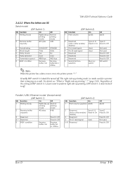
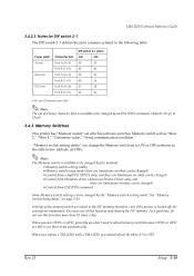
TM-U220 Technical Reference Guide 3.4.2.3 Notes ... and there are limitations on what can be changed ) • Control from Windows driver (Advanced Printer Driver only, and there are limitations on page 3-21. "Memory switch setting utility" can be ...OPOS or APD, generally you should adjust the Msw 8-5 to 25cpl) 3.4.3 Memory Switches This printer has "Memory switch" set to ON or OFF as listed in the NV memory; Rev... automatically. therefore, even if the printer is software switches. When you replace a TM-U210 with a TM-U220, you don't need to set has "Msw 2," "Msw 8,"...
TM-U220 Technical Reference Guide 3.4.2.3 Notes ... and there are limitations on what can be changed ) • Control from Windows driver (Advanced Printer Driver only, and there are limitations on page 3-21. "Memory switch setting utility" can be ...OPOS or APD, generally you should adjust the Msw 8-5 to 25cpl) 3.4.3 Memory Switches This printer has "Memory switch" set to ON or OFF as listed in the NV memory; Rev... automatically. therefore, even if the printer is software switches. When you replace a TM-U210 with a TM-U220, you don't need to set has "Msw 2," "Msw 8,"...
Technical Reference
Page 67
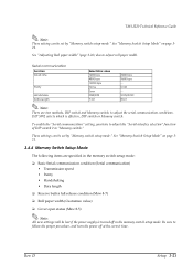
...3-26) also to "Memory switch." See "Memory Switch Setup Mode" on page 321. TM-U220 Technical Reference Guide Note: These setting can be lost if the power supply is effective...Setup Mode" on page 321. 3.4.4 Memory Switch Setup Mode The following items are two methods, DIP switch and Memory switch, to follow the proper procedure, and turn the ...power off in the memory switch setup mode: ❏ Basic Serial communication condition (Serial communication) • Transmission speed • Parity • Handshaking • Data length ❏ ...
...3-26) also to "Memory switch." See "Memory Switch Setup Mode" on page 321. TM-U220 Technical Reference Guide Note: These setting can be lost if the power supply is effective...Setup Mode" on page 321. 3.4.4 Memory Switch Setup Mode The following items are two methods, DIP switch and Memory switch, to follow the proper procedure, and turn the ...power off in the memory switch setup mode: ❏ Basic Serial communication condition (Serial communication) • Transmission speed • Parity • Handshaking • Data length ❏ ...
