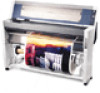
Service Manual
Page 7
EPSON Stylus Pro 9000 Paper Not Cut 46 Paper Not Straight 46 Reload Paper 47 Push Lever Down 47 Compartment Open 47 Ink Out 48 No Ink Cartridge 48 Remove Paper 48 Option I/F Error 48 Print Quality Troubleshooting 49 Missing Dots or Lines 49 No Ink Output from One or Both Printheads 50 Uneven Printing...Removing the Ink Pipe Covers 92 Separating the ink pipes and ink tubes 92 Removing the CR circuit board 93 Disconnecting the ink dampers 93 Removing the cable connection plate 94 Ink Tubing Reassembly 95 Installing the new cable connection plate 95 Positioning the tube guides and...
EPSON Stylus Pro 9000 Paper Not Cut 46 Paper Not Straight 46 Reload Paper 47 Push Lever Down 47 Compartment Open 47 Ink Out 48 No Ink Cartridge 48 Remove Paper 48 Option I/F Error 48 Print Quality Troubleshooting 49 Missing Dots or Lines 49 No Ink Output from One or Both Printheads 50 Uneven Printing...Removing the Ink Pipe Covers 92 Separating the ink pipes and ink tubes 92 Removing the CR circuit board 93 Disconnecting the ink dampers 93 Removing the cable connection plate 94 Ink Tubing Reassembly 95 Installing the new cable connection plate 95 Positioning the tube guides and...
Service Manual
Page 50
...is resolved: 1. If the printout quality still has not improved, perform the following : 1. Run a test print and check for output. 2. To test, place a syringe on page 128. The Capping Assembly may change...the Capping Assembly and rinse it back on page 73). If ink cannot be drawn through the damper, the ink valves may be drawn through , replace the Capping Assembly. 4. If ink cannot be...Make sure the tubing from one of the tubing that the signals are reaching the printheads. EPSON Stylus Pro 9000 NO INK OUTPUT FROM ONE OR BOTH PRINTHEADS If there is no ink output from the ...
...is resolved: 1. If the printout quality still has not improved, perform the following : 1. Run a test print and check for output. 2. To test, place a syringe on page 128. The Capping Assembly may change...the Capping Assembly and rinse it back on page 73). If ink cannot be drawn through the damper, the ink valves may be drawn through , replace the Capping Assembly. 4. If ink cannot be...Make sure the tubing from one of the tubing that the signals are reaching the printheads. EPSON Stylus Pro 9000 NO INK OUTPUT FROM ONE OR BOTH PRINTHEADS If there is no ink output from the ...

Service Manual
Page 61
EPSON Stylus Pro 9000 FRONT COVER REMOVAL Preparation: Remove the Maintenance Cover as described in Top Cover Removal on page 59. The Front Cover Assembly hinges on the cover's shaft are not secured and may slide off. 3. Left side Right side CP(W2) M3x8 screws Damper Assembly Figure 4-8. Removing the Damper Assembly Disassembly & ... Remove the Top Cover as described in Maintenance Cover Removal on page 58. Locations of the printer, and then remove the damper assembly. 2. Remove the Left and Right Side Covers as shown below. Remove the two screws (CP(W2) M3x8) securing the...
EPSON Stylus Pro 9000 FRONT COVER REMOVAL Preparation: Remove the Maintenance Cover as described in Top Cover Removal on page 59. The Front Cover Assembly hinges on the cover's shaft are not secured and may slide off. 3. Left side Right side CP(W2) M3x8 screws Damper Assembly Figure 4-8. Removing the Damper Assembly Disassembly & ... Remove the Top Cover as described in Maintenance Cover Removal on page 58. Locations of the printer, and then remove the damper assembly. 2. Remove the Left and Right Side Covers as shown below. Remove the two screws (CP(W2) M3x8) securing the...

Service Manual
Page 62
EPSON Stylus Pro 9000 ROLL COVER REMOVAL Preparation: Remove the Maintenance Cover as described in Left and Right Side Cover Removal on page 60. 1. Remove the two screws securing each end, that secure the mounting pins to the Roll Cover shaft. 3. Roll Cover Removal 62 Mounting Pin Left side of Roll Cover Damper Assembly Right side... page 59. Remove the four screws (CP(W2) M3x8), two on page 58. Remove the Top Cover as described in Maintenance Cover Removal on each damper assembly, and then remove the...
EPSON Stylus Pro 9000 ROLL COVER REMOVAL Preparation: Remove the Maintenance Cover as described in Left and Right Side Cover Removal on page 60. 1. Remove the two screws securing each end, that secure the mounting pins to the Roll Cover shaft. 3. Roll Cover Removal 62 Mounting Pin Left side of Roll Cover Damper Assembly Right side... page 59. Remove the four screws (CP(W2) M3x8), two on page 58. Remove the Top Cover as described in Maintenance Cover Removal on each damper assembly, and then remove the...

Service Manual
Page 73
... out. The ground wire connector attaches to the middle of the screw and the plastic Damper Holder. Pull out the dampers. Unhook the ink tubes from the damper holder. 6. To remove them only by first pulling its left side out toward you (forward), and then sliding the whole unit out toward the right. EPSON Stylus Pro 9000 4.
... out. The ground wire connector attaches to the middle of the screw and the plastic Damper Holder. Pull out the dampers. Unhook the ink tubes from the damper holder. 6. To remove them only by first pulling its left side out toward you (forward), and then sliding the whole unit out toward the right. EPSON Stylus Pro 9000 4.

Service Manual
Page 74
... for the other printhead if necessary. If the PG Cam Shaft does not partially block the line of sight of the printhead. When attaching the dampers to the printhead, follow the same order, left to right, as the PG Cam Shaft. Using needle-nosed pliers, remove the Tension Spring. 10. Remove... printhead ID is not installed properly. Remove the CB M3x6 screw, and then remove the printhead from the carriage. 9. Printhead Tension Spring and Screw Removal 8. EPSON Stylus Pro 9000 7.
... for the other printhead if necessary. If the PG Cam Shaft does not partially block the line of sight of the printhead. When attaching the dampers to the printhead, follow the same order, left to right, as the PG Cam Shaft. Using needle-nosed pliers, remove the Tension Spring. 10. Remove... printhead ID is not installed properly. Remove the CB M3x6 screw, and then remove the printhead from the carriage. 9. Printhead Tension Spring and Screw Removal 8. EPSON Stylus Pro 9000 7.

Service Manual
Page 93
Remove the CR circuit board. EPSON Stylus Pro 9000 REMOVING THE CR CIRCUIT BOARD 1. CR circuit board guide plate Cable support Ferrite core 3. Loosen the damper joint screws and remove the ink tubes from the FFCs to the inside of the CR circuit board guide and cable support.... pressing plate (black) that hold the ink tubes in use.) CR circuit board assembly Cable connection plate CR tape wire 1 CR tape wire 2 Damper joint screw 5. Cut the insulation (plastic) lock ties that secures the printhead FFCs to the junction board). Disassembly & Assembly 93 Remove the CR ...
Remove the CR circuit board. EPSON Stylus Pro 9000 REMOVING THE CR CIRCUIT BOARD 1. CR circuit board guide plate Cable support Ferrite core 3. Loosen the damper joint screws and remove the ink tubes from the FFCs to the inside of the CR circuit board guide and cable support.... pressing plate (black) that hold the ink tubes in use.) CR circuit board assembly Cable connection plate CR tape wire 1 CR tape wire 2 Damper joint screw 5. Cut the insulation (plastic) lock ties that secures the printhead FFCs to the junction board). Disassembly & Assembly 93 Remove the CR ...

Service Manual
Page 95
... overlap; Fold the right FFC slightly in the middle so the lengths of the two FFCs are straight and in the middle of the other. EPSON Stylus Pro 9000 4.7.1 Ink Tubing Reassembly This section describes how to the cable connection plate. 2. Re-attach the cable connection plate while making sure the Timing Fence is...' point of the tube guide. Make sure the three ink tubes in the H Top frame with two screws, and connect the ground to the ink dampers in the clips. Lay the left -side protective film on top of the FFCs, and then lay the new tube guide for the dark inks...
... overlap; Fold the right FFC slightly in the middle so the lengths of the two FFCs are straight and in the middle of the other. EPSON Stylus Pro 9000 4.7.1 Ink Tubing Reassembly This section describes how to the cable connection plate. 2. Re-attach the cable connection plate while making sure the Timing Fence is...' point of the tube guide. Make sure the three ink tubes in the H Top frame with two screws, and connect the ground to the ink dampers in the clips. Lay the left -side protective film on top of the FFCs, and then lay the new tube guide for the dark inks...

Service Manual
Page 98
... ink tube should pass through the slot on the right side of the cable connection plate. The ink tubes should be covered completely. 8. EPSON Stylus Pro 9000 CONNECTING THE INK TUBES AND DAMPERS 1. Arrange the dark series ink tubes from the tube guide to twist the three tubes. 3. Take one ink tube and apply cleaning...
... ink tube should pass through the slot on the right side of the cable connection plate. The ink tubes should be covered completely. 8. EPSON Stylus Pro 9000 CONNECTING THE INK TUBES AND DAMPERS 1. Arrange the dark series ink tubes from the tube guide to twist the three tubes. 3. Take one ink tube and apply cleaning...

Service Manual
Page 100
EPSON Stylus Pro 9000 CONNECTING THE CARRIAGE FFCS TO THE RELAY CIRCUIT BOARD 1. Fold the FFCs into three sections as the amount of the doublesided adhesive tape on page 116). Fill" in the Cleaning menu on page 128 of printed colors in Maintenance Mode 2 on page 130. 5. See Carriage Cover Height Adjustment on... adhesive tape at two places: the wall surface toward the right frame and the folded section near the center. 2. As shown in the dampers. Make sure there are aligned and peel off the backing of the first one. 3. Attach the carriage cover and perform the carriage cover ...
EPSON Stylus Pro 9000 CONNECTING THE CARRIAGE FFCS TO THE RELAY CIRCUIT BOARD 1. Fold the FFCs into three sections as the amount of the doublesided adhesive tape on page 116). Fill" in the Cleaning menu on page 128 of printed colors in Maintenance Mode 2 on page 130. 5. See Carriage Cover Height Adjustment on... adhesive tape at two places: the wall surface toward the right frame and the folded section near the center. 2. As shown in the dampers. Make sure there are aligned and peel off the backing of the first one. 3. Attach the carriage cover and perform the carriage cover ...

Service Manual
Page 174
EPSON Stylus Pro 9000 Table 7-12. Part Code Description Qty PRINTER MECHANISM 202 2030089 P FRONT DETECTOR ASSY 1 PRINTER MECHANISM 203 1044274 Y DRIVEN PULLEY ASSY 1 PRINTER MECHANISM 204 1044275...PULLEY ASSY 1 PRINTER MECHANISM 208 1044279 DETECTOR ARM 1 PRINTER MECHANISM 209 1044285 STEEL BELT 1 PRINTER MECHANISM 213 1038961 ROLLER,DRIVEN;D 67 PRINTER MECHANISM 302 1044238 DAMPER ASSY., 6 PRINTER MECHANISM 303 F055050 PRINTHEAD,IJ192-0AE (for light ink-right) 1 PRINTER MECHANISM 304 1044288 HEAD TAPE CABLE 2 PRINTER MECHANISM 305 F055040 ...
EPSON Stylus Pro 9000 Table 7-12. Part Code Description Qty PRINTER MECHANISM 202 2030089 P FRONT DETECTOR ASSY 1 PRINTER MECHANISM 203 1044274 Y DRIVEN PULLEY ASSY 1 PRINTER MECHANISM 204 1044275...PULLEY ASSY 1 PRINTER MECHANISM 208 1044279 DETECTOR ARM 1 PRINTER MECHANISM 209 1044285 STEEL BELT 1 PRINTER MECHANISM 213 1038961 ROLLER,DRIVEN;D 67 PRINTER MECHANISM 302 1044238 DAMPER ASSY., 6 PRINTER MECHANISM 303 F055050 PRINTHEAD,IJ192-0AE (for light ink-right) 1 PRINTER MECHANISM 304 1044288 HEAD TAPE CABLE 2 PRINTER MECHANISM 305 F055040 ...

Service Manual
Page 175
...MOTOR,ASF 1 Table 7-12. Part Code Description Qty PRINTER MECHANISM 412 1012618 DAMPER,CR 3 PRINTER MECHANISM 413 1038605 PLANE WASHER,3.3*1.5*8,S/NA 3 PRINTER MECHANISM 414 1017596 SHAFT,DAMPER,CR;B 3 PRINTER MECHANISM 415 1037461 FASTEN PLATE,MOTOR,ASF 1 PRINTER MECHANISM ... MECHANISM 513 2030096 HOLDER R TAPE CABLE 1 Appendix 175 Parts List (continued) Block Name Ref No. EPSON Stylus Pro 9000 Block Name PRINTER MECHANISM PRINTER MECHANISM PRINTER MECHANISM PRINTER MECHANISM PRINTER MECHANISM PRINTER MECHANISM PRINTER MECHANISM PRINTER MECHANISM PRINTER...
...MOTOR,ASF 1 Table 7-12. Part Code Description Qty PRINTER MECHANISM 412 1012618 DAMPER,CR 3 PRINTER MECHANISM 413 1038605 PLANE WASHER,3.3*1.5*8,S/NA 3 PRINTER MECHANISM 414 1017596 SHAFT,DAMPER,CR;B 3 PRINTER MECHANISM 415 1037461 FASTEN PLATE,MOTOR,ASF 1 PRINTER MECHANISM ... MECHANISM 513 2030096 HOLDER R TAPE CABLE 1 Appendix 175 Parts List (continued) Block Name Ref No. EPSON Stylus Pro 9000 Block Name PRINTER MECHANISM PRINTER MECHANISM PRINTER MECHANISM PRINTER MECHANISM PRINTER MECHANISM PRINTER MECHANISM PRINTER MECHANISM PRINTER MECHANISM PRINTER...

Service Manual
Page 176
Part Code Description Qty PRINTER MECHANISM 530 1044346 OIL DAMPER 2 PRINTER MECHANISM 531 1044347 I/H SPACER 4 PRINTER MECHANISM 532 1044348 I /H LEVER KNOB R 1 PRINTER MECHANISM 527 1044343 BULB KNOB 2 PRINTER MECHANISM 528 1044344 BULB MANUAL CAM 2 Table 7-12. EPSON Stylus Pro 9000 Table 7-12. Parts List (continued) Block Name Ref No. Parts List (continued) Block Name Ref No...
Part Code Description Qty PRINTER MECHANISM 530 1044346 OIL DAMPER 2 PRINTER MECHANISM 531 1044347 I/H SPACER 4 PRINTER MECHANISM 532 1044348 I /H LEVER KNOB R 1 PRINTER MECHANISM 527 1044343 BULB KNOB 2 PRINTER MECHANISM 528 1044344 BULB MANUAL CAM 2 Table 7-12. EPSON Stylus Pro 9000 Table 7-12. Parts List (continued) Block Name Ref No. Parts List (continued) Block Name Ref No...

