Installation Instructions (All Languages)
Page 1
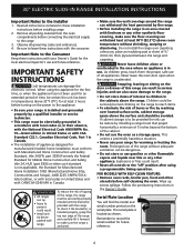
30" ELECTRIC SLIDE-IN RANGE INSTALLATION INSTRUCTIONS United States INSTALLATION AND SERVICE MUST BE PERFORMED BY A QUALIFIED INSTALLER. READ AND SAVE THESE INSTRUCTIONS FOR FUTURE REFERENCE. Canada For existing 29" (...çais - pages 25-36 FOR YOUR SAFETY: Do not store or use gasoline or other appliance. WIDTH (Under Cooktop) C. TOTAL DEPTH TO FRONT OF RANGE 28 5/16" (71,9 cm) E. with backguard G.
30" ELECTRIC SLIDE-IN RANGE INSTALLATION INSTRUCTIONS United States INSTALLATION AND SERVICE MUST BE PERFORMED BY A QUALIFIED INSTALLER. READ AND SAVE THESE INSTRUCTIONS FOR FUTURE REFERENCE. Canada For existing 29" (...çais - pages 25-36 FOR YOUR SAFETY: Do not store or use gasoline or other appliance. WIDTH (Under Cooktop) C. TOTAL DEPTH TO FRONT OF RANGE 28 5/16" (71,9 cm) E. with backguard G.
Installation Instructions (All Languages)
Page 2
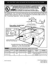
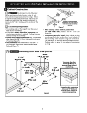
30" ELECTRIC SLIDE-IN RANGE INSTALLATION INSTRUCTIONS NOTE: 1. Raise leveling legs and the rear adjustable wheels at a higher ... than the cabinet height (see Note 4) FRONT OF CABINET 1 1/8" (2,86 cm) F Ref. TOTAL DEPTH TO FRONT OF RANGE 28 5/16" (71,9 cm) E. HEIGHT B. CUTOUT DEPTH 21 3/4" (55,2 cm) Min. 22 1/8" (56,2 cm) Max 24..." (61 cm) Min. Do not seal the range to the side cabinets. 3. 24" (61 cm) minimum clearance between the range and the wall. 2. COOKTOP WIDTH 35 3/4" (90,8 cm) 30" (76,2 cm) 36 5/8" (93 cm) 31...
30" ELECTRIC SLIDE-IN RANGE INSTALLATION INSTRUCTIONS NOTE: 1. Raise leveling legs and the rear adjustable wheels at a higher ... than the cabinet height (see Note 4) FRONT OF CABINET 1 1/8" (2,86 cm) F Ref. TOTAL DEPTH TO FRONT OF RANGE 28 5/16" (71,9 cm) E. HEIGHT B. CUTOUT DEPTH 21 3/4" (55,2 cm) Min. 22 1/8" (56,2 cm) Max 24..." (61 cm) Min. Do not seal the range to the side cabinets. 3. 24" (61 cm) minimum clearance between the range and the wall. 2. COOKTOP WIDTH 35 3/4" (90,8 cm) 30" (76,2 cm) 36 5/8" (93 cm) 31...
Installation Instructions (All Languages)
Page 3
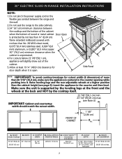
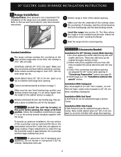
... the installation, MAKE SURE that the height from the floor to the underside Space for the transport. 5 Slide the unit into the cabinet. Level the range using Shave the two (2) front leveling Raised 1 ½" Max. (3.8 cm Max.) legs and the two (2) Edge 3 adjustable leveling wheel, to Clear...is supported by the two front leveling legs and the two adjustable leveling wheels and NOT by the cooktop. 30" ELECTRIC SLIDE-IN RANGE INSTALLATION INSTRUCTIONS To avoid breakage: Do NOT handle or manipulate the unit by at least 1/16" taller than the tallest cabinet measurement...
... the installation, MAKE SURE that the height from the floor to the underside Space for the transport. 5 Slide the unit into the cabinet. Level the range using Shave the two (2) front leveling Raised 1 ½" Max. (3.8 cm Max.) legs and the two (2) Edge 3 adjustable leveling wheel, to Clear...is supported by the two front leveling legs and the two adjustable leveling wheels and NOT by the cooktop. 30" ELECTRIC SLIDE-IN RANGE INSTALLATION INSTRUCTIONS To avoid breakage: Do NOT handle or manipulate the unit by at least 1/16" taller than the tallest cabinet measurement...
Installation Instructions (All Languages)
Page 4
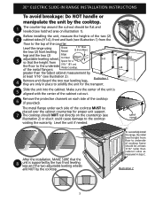
...(part 280)] or when such standard is unattended. To check if the bracket(s), is installed properly, grasp the top rear edge of the range without shrinking, warping or discoloring. Never leave children alone or unattended in the area where an appliance is anchored. • Make sure the ...the power to reach items. • To eliminate the risk of burns or fire by a qualified installer or service technician. • This range must be reduce by properly installed anti-tip bracket(s) provided with the consumer. Explosions or fires could result. • Install antitip device packed with...
...(part 280)] or when such standard is unattended. To check if the bracket(s), is installed properly, grasp the top rear edge of the range without shrinking, warping or discoloring. Never leave children alone or unattended in the area where an appliance is anchored. • Make sure the ...the power to reach items. • To eliminate the risk of burns or fire by a qualified installer or service technician. • This range must be reduce by properly installed anti-tip bracket(s) provided with the consumer. Explosions or fires could result. • Install antitip device packed with...
Installation Instructions (All Languages)
Page 5
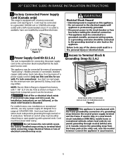
...). For mobile homes, new installations or recreational vehicles, use 50A cord kits for connecting the power supply cord to terminal block while connecting range. Cord must have either closed loop or open spade lug with a 50A recommended circuit. Failure to do not permit grounding through neutral) ... strap between the neutral power supply terminal and the frame. Electrical failure or loss of fire or electrical shock exists if an incorrect size range cord kit is used in USA, in a fire, personal injury or electrical shock. 3. If used , the Installation Instructions are not followed...
...). For mobile homes, new installations or recreational vehicles, use 50A cord kits for connecting the power supply cord to terminal block while connecting range. Cord must have either closed loop or open spade lug with a 50A recommended circuit. Failure to do not permit grounding through neutral) ... strap between the neutral power supply terminal and the frame. Electrical failure or loss of fire or electrical shock exists if an incorrect size range cord kit is used in USA, in a fire, personal injury or electrical shock. 3. If used , the Installation Instructions are not followed...
Installation Instructions (All Languages)
Page 6
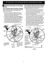
...(3.5cm) Dia. Remove the 3 screws at This Location Neutral (White Wire) Ground (Bare Copper Wire) To 240 V Receptacle NOTE: Be sure to expose range terminal connection block (see figure 3). 3. Direct Connection Hole. Punch Out Knockout for 1 3/8" (3.5 cm) Dia. Cord Kit Hole. Using the nuts supplied with... the lower end of the rear wire cover, then bend the lower end of the terminal block, and connect the other wires to expose range terminal connection block (see Figure 4): 1. Using the nuts supplied in the frame where the ground strap was removed (see Figure 3): 1. ...
...(3.5cm) Dia. Remove the 3 screws at This Location Neutral (White Wire) Ground (Bare Copper Wire) To 240 V Receptacle NOTE: Be sure to expose range terminal connection block (see figure 3). 3. Direct Connection Hole. Punch Out Knockout for 1 3/8" (3.5 cm) Dia. Cord Kit Hole. Using the nuts supplied with... the lower end of the rear wire cover, then bend the lower end of the terminal block, and connect the other wires to expose range terminal connection block (see Figure 4): 1. Using the nuts supplied in the frame where the ground strap was removed (see Figure 3): 1. ...
Installation Instructions (All Languages)
Page 7
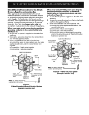
30" ELECTRIC SLIDE-IN RANGE INSTALLATION INSTRUCTIONS Direct Electrical Connection to the Circuit Breaker, Fuse Box or Junction Box If the appliance is connected directly to 4-wire electrical system (see ...
30" ELECTRIC SLIDE-IN RANGE INSTALLATION INSTRUCTIONS Direct Electrical Connection to the Circuit Breaker, Fuse Box or Junction Box If the appliance is connected directly to 4-wire electrical system (see ...
Installation Instructions (All Languages)
Page 8
... cm) back at front corners of countertop. • Formed front-edged countertops must be level. If the countertop is not level, the range will not be level for satisfactory baking results. The oven must have molded edge shaved flat 3/4" (1.9 cm) from each front corner and/or... rounded edge flattened (Figure 7). 30" ELECTRIC SLIDE-IN RANGE INSTALLATION INSTRUCTIONS 4. Place a level on edge of countertop opening. 8 Figure 7 • If the existing cutout width is greater than 30 1/16" (...
... cm) back at front corners of countertop. • Formed front-edged countertops must be level. If the countertop is not level, the range will not be level for satisfactory baking results. The oven must have molded edge shaved flat 3/4" (1.9 cm) from each front corner and/or... rounded edge flattened (Figure 7). 30" ELECTRIC SLIDE-IN RANGE INSTALLATION INSTRUCTIONS 4. Place a level on edge of countertop opening. 8 Figure 7 • If the existing cutout width is greater than 30 1/16" (...
Installation Instructions (All Languages)
Page 9
...trims can be level. Installation With Side Panels A Side Panels kit can be ordered through a Service Center. 30" ELECTRIC SLIDE-IN RANGE INSTALLATION INSTRUCTIONS 5. Range Installation Important Note: Door removal is to replace the actual side trims with the new ones. 3.Check if the countertop and cabinet opening ...are 6 only in front of the cooktop clears 11 the countertop. Refer to range cooktop. Make sure that are adjacent to the Use and Care Guide for installation of damaging your new side trims to be installed must...
...trims can be level. Installation With Side Panels A Side Panels kit can be ordered through a Service Center. 30" ELECTRIC SLIDE-IN RANGE INSTALLATION INSTRUCTIONS 5. Range Installation Important Note: Door removal is to replace the actual side trims with the new ones. 3.Check if the countertop and cabinet opening ...are 6 only in front of the cooktop clears 11 the countertop. Refer to range cooktop. Make sure that are adjacent to the Use and Care Guide for installation of damaging your new side trims to be installed must...
Installation Instructions (All Languages)
Page 10
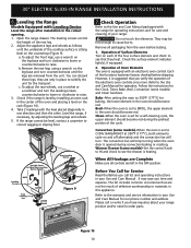
...(Figure 9). Refer to cause burns. The leveling screws control the height of the functions has been factory checked before testing. 1. If the range cannot be hot enough to the warranty and service information in place to solidify the unit for the Clock, Timer, Bake, Broil, Convection ...lower or clockwise to CONV. Please call list and operating instructions in the oven should become red. Figure 10 10 30" ELECTRIC SLIDE-IN RANGE INSTALLATION INSTRUCTIONS 6. You can discard those legs, they heat. Before You Call for a self-cleaning cycle, the upper element should become ...
...(Figure 9). Refer to cause burns. The leveling screws control the height of the functions has been factory checked before testing. 1. If the range cannot be hot enough to the warranty and service information in place to solidify the unit for the Clock, Timer, Bake, Broil, Convection ...lower or clockwise to CONV. Please call list and operating instructions in the oven should become red. Figure 10 10 30" ELECTRIC SLIDE-IN RANGE INSTALLATION INSTRUCTIONS 6. You can discard those legs, they heat. Before You Call for a self-cleaning cycle, the upper element should become ...
Installation Instructions (All Languages)
Page 11
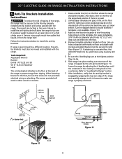
...BRACKET (CL = Center line) REAR WALL Door Cabinet Anti-Tip Bracket Rear of the cooktop is no wall. 2. Failure to prevent range from the range itself. For easier installation, 3/16"(0,48 cm) diameter pilot holes 1/2"(1,27 cm) deep can be drilled into place making sure structure of... floor at the highest position they can be . 6. Refer to concrete floor, first drill 3/16"(0,48 cm) dia. 30" ELECTRIC SLIDE-IN RANGE INSTALLATION INSTRUCTIONS 8. Tools Required: Adjustable Wrench Ratchet Drill & 1/8"(0,32 cm) bit 5/16" (0,8 cm) Nutdriver Level The anti-tip bracket attaches to...
...BRACKET (CL = Center line) REAR WALL Door Cabinet Anti-Tip Bracket Rear of the cooktop is no wall. 2. Failure to prevent range from the range itself. For easier installation, 3/16"(0,48 cm) diameter pilot holes 1/2"(1,27 cm) deep can be drilled into place making sure structure of... floor at the highest position they can be . 6. Refer to concrete floor, first drill 3/16"(0,48 cm) dia. 30" ELECTRIC SLIDE-IN RANGE INSTALLATION INSTRUCTIONS 8. Tools Required: Adjustable Wrench Ratchet Drill & 1/8"(0,32 cm) bit 5/16" (0,8 cm) Nutdriver Level The anti-tip bracket attaches to...

Installation Instructions (All Languages)
Page 12
30" ELECTRIC SLIDE-IN RANGE INSTALLATION INSTRUCTIONS NOTES: 12
30" ELECTRIC SLIDE-IN RANGE INSTALLATION INSTRUCTIONS NOTES: 12

Product Specifications Sheet (English)
Page 1
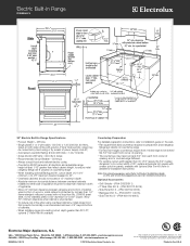
...PN # 318251611 2" Rear Filler Kit, Side Panel Kit, Backguard Kit, Side Trim Kit - Wall Ovens Warmer Drawers Cooktops Built-In Ranges Freestanding Ranges Microwaves Electric Built-In Range EI30ES55J S Luxury-Glide® Oven Rack With a ball bearing system, oven rack is functional. 30" ELECTRIC BUILT-IN... RANGE Control Panel Features IQ-Touch™ Electronic Oven Control Yes Glide-2-Set™ Element Controls Yes Keypad Entry of Time & ...
...PN # 318251611 2" Rear Filler Kit, Side Panel Kit, Backguard Kit, Side Trim Kit - Wall Ovens Warmer Drawers Cooktops Built-In Ranges Freestanding Ranges Microwaves Electric Built-In Range EI30ES55J S Luxury-Glide® Oven Rack With a ball bearing system, oven rack is functional. 30" ELECTRIC BUILT-IN... RANGE Control Panel Features IQ-Touch™ Electronic Oven Control Yes Glide-2-Set™ Element Controls Yes Keypad Entry of Time & ...
Product Specifications Sheet (English)
Page 2
...) • electroluxappliances.com CANADA • 5855 Terry Fox Way • Mississauga, ON L5V 3E4 • 1-800-265-8352 • electroluxappliances.ca EI30ES55J 09/10 © 2010 Electrolux Home Products, Inc. Electric Built-In Range EI30ES55J S 30" Electric Built-In Range Specifications • Product Weight - 238 Lbs. • Single phase 3- Printed in all directions and adjustable...
...) • electroluxappliances.com CANADA • 5855 Terry Fox Way • Mississauga, ON L5V 3E4 • 1-800-265-8352 • electroluxappliances.ca EI30ES55J 09/10 © 2010 Electrolux Home Products, Inc. Electric Built-In Range EI30ES55J S 30" Electric Built-In Range Specifications • Product Weight - 238 Lbs. • Single phase 3- Printed in all directions and adjustable...


