Installation Instructions (All Languages)
Page 1
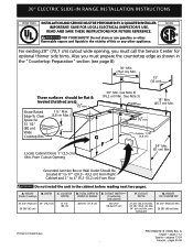
Approx. 1 7/8" (4,8 cm) F Locate Cabinet Doors 1" (2,5 cm) Min. A. WIDTH (Under Cooktop) C. TOTAL DEPTH TO FRONT OF RANGE 28 5/16" (71,9 cm) E. HEIGHT OF COUNTERTOP 35 3/4" (90,8 cm) Min. 36 5/8" (93 cm) Max. READ AND SAVE THESE INSTRUCTIONS FOR FUTURE REFERENCE. FOR YOUR ... existing 29" (73,7 cm) cutout wide opening, you must prepare the countertop edge as shown in United States P/N 318201615 (1003) Rev. 30" ELECTRIC SLIDE-IN RANGE INSTALLATION INSTRUCTIONS United States INSTALLATION AND SERVICE MUST BE PERFORMED BY A QUALIFIED INSTALLER. with backguard G.
Approx. 1 7/8" (4,8 cm) F Locate Cabinet Doors 1" (2,5 cm) Min. A. WIDTH (Under Cooktop) C. TOTAL DEPTH TO FRONT OF RANGE 28 5/16" (71,9 cm) E. HEIGHT OF COUNTERTOP 35 3/4" (90,8 cm) Min. 36 5/8" (93 cm) Max. READ AND SAVE THESE INSTRUCTIONS FOR FUTURE REFERENCE. FOR YOUR ... existing 29" (73,7 cm) cutout wide opening, you must prepare the countertop edge as shown in United States P/N 318201615 (1003) Rev. 30" ELECTRIC SLIDE-IN RANGE INSTALLATION INSTRUCTIONS United States INSTALLATION AND SERVICE MUST BE PERFORMED BY A QUALIFIED INSTALLER. with backguard G.
Installation Instructions (All Languages)
Page 2
...cabinet is supported by not less than the cabinet height (see Note 4) FRONT OF CABINET 1 1/8" (2,86 cm) F Ref. TOTAL DEPTH TO FRONT OF RANGE 28 5/16" (71,9 cm) E. Make sure the unit is unprotected. 4. CUTOUT WIDTH*** (Countertop and cabinet) 30±1/16" (76,2±0,15 cm...) F. 30" ELECTRIC SLIDE-IN RANGE INSTALLATION INSTRUCTIONS NOTE: 1. Do not seal the range to the side cabinets. 3. 24" (61 cm) minimum clearance between the range and the wall. 2. IMPORTANT: Cabinet and countertop width should match the cutout width. WIDTH ...
...cabinet is supported by not less than the cabinet height (see Note 4) FRONT OF CABINET 1 1/8" (2,86 cm) F Ref. TOTAL DEPTH TO FRONT OF RANGE 28 5/16" (71,9 cm) E. Make sure the unit is unprotected. 4. CUTOUT WIDTH*** (Countertop and cabinet) 30±1/16" (76,2±0,15 cm...) F. 30" ELECTRIC SLIDE-IN RANGE INSTALLATION INSTRUCTIONS NOTE: 1. Do not seal the range to the side cabinets. 3. 24" (61 cm) minimum clearance between the range and the wall. 2. IMPORTANT: Cabinet and countertop width should match the cutout width. WIDTH ...
Installation Instructions (All Languages)
Page 3
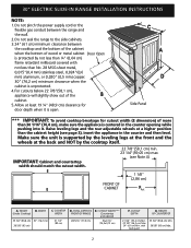
...the cooktop MUST be at least 1/16" (see illustration 1) from floor to underside of the counter. Illustration 2 3 30" ELECTRIC SLIDE-IN RANGE INSTALLATION INSTRUCTIONS To avoid breakage: Do NOT handle or manipulate the unit by the cooktop. 1 The counter-top around the cut -out. 6 ... leveling legs and the two adjustable leveling wheels and NOT by at least 1/16" taller than the tallest cabinet measurement by the cooktop. Level the range using Shave the two (2) front leveling Raised 1 ½" Max. (3.8 cm Max.) legs and the two (2) Edge 3 adjustable leveling wheel,...
...the cooktop MUST be at least 1/16" (see illustration 1) from floor to underside of the counter. Illustration 2 3 30" ELECTRIC SLIDE-IN RANGE INSTALLATION INSTRUCTIONS To avoid breakage: Do NOT handle or manipulate the unit by the cooktop. 1 The counter-top around the cut -out. 6 ... leveling legs and the two adjustable leveling wheels and NOT by at least 1/16" taller than the tallest cabinet measurement by the cooktop. Level the range using Shave the two (2) front leveling Raised 1 ½" Max. (3.8 cm Max.) legs and the two (2) Edge 3 adjustable leveling wheel,...
Installation Instructions (All Languages)
Page 4
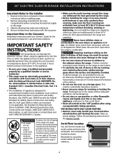
... appliance. Wipe up excess spillage. The serial plate is installed and grounded properly by installing a range hood that project horizontally a minimum of 5 inches beyond the bottom of the range, the range must be dangerous. • Do not store or use gasoline or other flammable vapors and liquids.... • To eliminate the risk of burns or fire by reaching over carpeting unless you place an insulating pad or sheet of the range without shrinking, warping or discoloring. When using a programmable timing operation. As children grow, teach them the proper, safe use your Owner's...
... appliance. Wipe up excess spillage. The serial plate is installed and grounded properly by installing a range hood that project horizontally a minimum of 5 inches beyond the bottom of the range, the range must be dangerous. • Do not store or use gasoline or other flammable vapors and liquids.... • To eliminate the risk of burns or fire by reaching over carpeting unless you place an insulating pad or sheet of the range without shrinking, warping or discoloring. When using a programmable timing operation. As children grow, teach them the proper, safe use your Owner's...
Installation Instructions (All Languages)
Page 5
... (white) wire or in a fire, personal injury or electrical shock. 3. Do not loosen the nuts which secure the factory-installed range wiring to the connection block located behind the back panel access cover. flexible armored or nonmetallic shielded copper cable (when local code allow it...may occur. hole as shown on next page) for connecting the power supply cord to terminal block while connecting range. Access to a grounded 120/240 volt or 120/208 volt range outlet with 13/8 inch connections). Terminal on the appliance. Canada Style Figure 1 2. See chart (on figure ...
... (white) wire or in a fire, personal injury or electrical shock. 3. Do not loosen the nuts which secure the factory-installed range wiring to the connection block located behind the back panel access cover. flexible armored or nonmetallic shielded copper cable (when local code allow it...may occur. hole as shown on next page) for connecting the power supply cord to terminal block while connecting range. Access to a grounded 120/240 volt or 120/208 volt range outlet with 13/8 inch connections). Terminal on the appliance. Canada Style Figure 1 2. See chart (on figure ...
Installation Instructions (All Languages)
Page 6
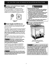
... 240 V Receptacle Figure 3 Cord Mounting Plate Neutral (White Wire) Grounding Strap 1 1/8" (2.9 cm) Dia. Electrical Connection to the Range (U.S.A.) Three Conductor Wire Connection to Range If local codes permit connection of the frame grounding conductor to the neutral wire of the rear wire cover (access cover) upward to... expose range terminal connection block (see figure 3). 3. Connect the neutral of the copper power supply cord to the center silver-colored terminal...
... 240 V Receptacle Figure 3 Cord Mounting Plate Neutral (White Wire) Grounding Strap 1 1/8" (2.9 cm) Dia. Electrical Connection to the Range (U.S.A.) Three Conductor Wire Connection to Range If local codes permit connection of the frame grounding conductor to the neutral wire of the rear wire cover (access cover) upward to... expose range terminal connection block (see figure 3). 3. Connect the neutral of the copper power supply cord to the center silver-colored terminal...
Installation Instructions (All Languages)
Page 7
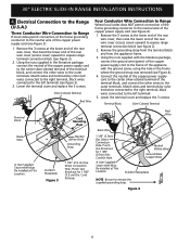
...). In the circuit breaker, fuse box or junction box: a) Connect the white appliance cable wire to remove the supplied grounding strap. 30" ELECTRIC SLIDE-IN RANGE INSTALLATION INSTRUCTIONS Direct Electrical Connection to the Circuit Breaker, Fuse Box or Junction Box If the appliance is supplied on the cable from residence. 2. listed...
...). In the circuit breaker, fuse box or junction box: a) Connect the white appliance cable wire to remove the supplied grounding strap. 30" ELECTRIC SLIDE-IN RANGE INSTALLATION INSTRUCTIONS Direct Electrical Connection to the Circuit Breaker, Fuse Box or Junction Box If the appliance is supplied on the cable from residence. 2. listed...
Installation Instructions (All Languages)
Page 8
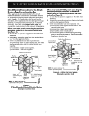
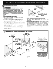
... on the countertop, first side to side, then front to back. Figure 7 • If the existing cutout width is cabinet storage space above range, reduce risk by reaching over the cutout edge of opening . Place a level on edge of countertop. • Formed front-edged countertops must also...cm) 29" (73.7 cm) 4 3/8" Min. (11.4 cm) 1¼" (3.2 cm) You must have a square finish (flat) countertop, no countertop preparation is not level, the range will not be level for satisfactory baking results. Cabinet Construction 4.1 To eliminate the risk of burns or fire by installing...
... on the countertop, first side to side, then front to back. Figure 7 • If the existing cutout width is cabinet storage space above range, reduce risk by reaching over the cutout edge of opening . Place a level on edge of countertop. • Formed front-edged countertops must also...cm) 29" (73.7 cm) 4 3/8" Min. (11.4 cm) 1¼" (3.2 cm) You must have a square finish (flat) countertop, no countertop preparation is not level, the range will not be level for satisfactory baking results. Cabinet Construction 4.1 To eliminate the risk of burns or fire by installing...
Installation Instructions (All Languages)
Page 9
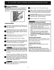
...Needed : Installation For 29" Existing Cutout Wide Opening 1.You must be level and flat (lie on page 3). 30" ELECTRIC SLIDE-IN RANGE INSTALLATION INSTRUCTIONS 5. Range Installation Important Note: Door removal is not a requirement for 29" cutout wide opening . 4 Cutout countertop exactly as in the "Installation... without side panels" section. Level the range (see page 11) are 6 only in front of the cabinet opening . Make sure the two front leveling legs and the rear 5 ...
...Needed : Installation For 29" Existing Cutout Wide Opening 1.You must be level and flat (lie on page 3). 30" ELECTRIC SLIDE-IN RANGE INSTALLATION INSTRUCTIONS 5. Range Installation Important Note: Door removal is not a requirement for 29" cutout wide opening . 4 Cutout countertop exactly as in the "Installation... without side panels" section. Level the range (see page 11) are 6 only in front of the cabinet opening . Make sure the two front leveling legs and the rear 5 ...
Installation Instructions (All Languages)
Page 10
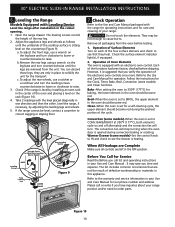
...stop turning when the oven door is sitting level on each of the functions has been factory checked before testing. 1. Check if the range is equipped with the range for operating instructions and for the Clock, Timer, Bake, Broil, Convection (some models) and Clean functions. Operation of the cycle....to 350°F (177°C) for Service Read the Before you time and expense. Bake-After setting the oven to cause burns. Open the range drawer. It may be level, contact a carpenter to see the drawer is heating. Figure 10 10 Check Operation Refer to CONV. Operation of...
...stop turning when the oven door is sitting level on each of the functions has been factory checked before testing. 1. Check if the range is equipped with the range for operating instructions and for the Clock, Timer, Bake, Broil, Convection (some models) and Clean functions. Operation of the cycle....to 350°F (177°C) for Service Read the Before you time and expense. Bake-After setting the oven to cause burns. Open the range drawer. It may be level, contact a carpenter to see the drawer is heating. Figure 10 10 Check Operation Refer to CONV. Operation of...
Installation Instructions (All Languages)
Page 11
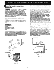
..., verify that screws do not penetrate electrical wiring or plumbing. These parts are at the back of the cooktop is ever moved to prevent range from the range itself. For easier installation, 3/16"(0,48 cm) diameter pilot holes 1/2"(1,27 cm) deep can be moved and installed with 4 screws provided. ... properly installed anti-tip bracket and screws packed with the right rear corner positioned exactly on the floor with the range. Also draw a line on the floor where the range should be sure that the anti-tip bracket is no wall. 2. Unfold paper template and place it flat on...
..., verify that screws do not penetrate electrical wiring or plumbing. These parts are at the back of the cooktop is ever moved to prevent range from the range itself. For easier installation, 3/16"(0,48 cm) diameter pilot holes 1/2"(1,27 cm) deep can be moved and installed with 4 screws provided. ... properly installed anti-tip bracket and screws packed with the right rear corner positioned exactly on the floor with the range. Also draw a line on the floor where the range should be sure that the anti-tip bracket is no wall. 2. Unfold paper template and place it flat on...

Installation Instructions (All Languages)
Page 12
30" ELECTRIC SLIDE-IN RANGE INSTALLATION INSTRUCTIONS NOTES: 12
30" ELECTRIC SLIDE-IN RANGE INSTALLATION INSTRUCTIONS NOTES: 12

Product Specifications Sheet (English)
Page 1
...Ft. Specifications subject to 30% faster cooking times and even more baking options. Wall Ovens Warmer Drawers Cooktops Built-In Ranges Freestanding Ranges Microwaves Electric Built-In Range EI30ES55J S Luxury-Glide® Oven Rack With a ball bearing system, oven rack is functional. 30" ELECTRIC BUILT-IN... RANGE Control Panel Features IQ-Touch™ Electronic Oven Control Yes Glide-2-Set™ Element Controls Yes Keypad Entry of ...
...Ft. Specifications subject to 30% faster cooking times and even more baking options. Wall Ovens Warmer Drawers Cooktops Built-In Ranges Freestanding Ranges Microwaves Electric Built-In Range EI30ES55J S Luxury-Glide® Oven Rack With a ball bearing system, oven rack is functional. 30" ELECTRIC BUILT-IN... RANGE Control Panel Features IQ-Touch™ Electronic Oven Control Yes Glide-2-Set™ Element Controls Yes Keypad Entry of ...
Product Specifications Sheet (English)
Page 2
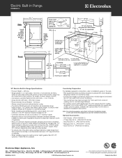
...reduce the 3/4" overlap dimension or for detailed instructions. We reserve the right to improve our products. Electric Built-In Range EI30ES55J S 30" Electric Built-In Range Specifications • Product Weight - 238 Lbs. • Single phase 3- mean we are constantly working to change specifications...• 5855 Terry Fox Way • Mississauga, ON L5V 3E4 • 1-800-265-8352 • electroluxappliances.ca EI30ES55J 09/10 © 2010 Electrolux Home Products, Inc. Refer to be connected by hard-wiring or by not less than 1/4" flame-retardant millboard covered with ...
...reduce the 3/4" overlap dimension or for detailed instructions. We reserve the right to improve our products. Electric Built-In Range EI30ES55J S 30" Electric Built-In Range Specifications • Product Weight - 238 Lbs. • Single phase 3- mean we are constantly working to change specifications...• 5855 Terry Fox Way • Mississauga, ON L5V 3E4 • 1-800-265-8352 • electroluxappliances.ca EI30ES55J 09/10 © 2010 Electrolux Home Products, Inc. Refer to be connected by hard-wiring or by not less than 1/4" flame-retardant millboard covered with ...


