Installation Instructions
Page 1
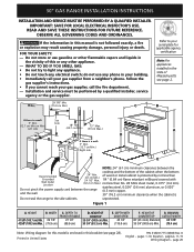
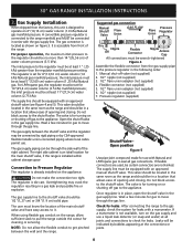
... FOR LOCAL ELECTRICAL INSPECTOR'S USE. Installation and service must be performed by not less than (61 cm Min.) 24 1/2" Max. 1/4" (0.64 cm) flame retardant millboard covered with Wall Outlet Location (62.2 cm Max.) not less than No. 28 MSG sheet metal, 0.015" (0.4 mm) stainless steel, 0.024" (0.6 mm) aluminum, or 0.020" Do not pinch the power supply cord between the cooktop and the...
... FOR LOCAL ELECTRICAL INSPECTOR'S USE. Installation and service must be performed by not less than (61 cm Min.) 24 1/2" Max. 1/4" (0.64 cm) flame retardant millboard covered with Wall Outlet Location (62.2 cm Max.) not less than No. 28 MSG sheet metal, 0.015" (0.4 mm) stainless steel, 0.024" (0.6 mm) aluminum, or 0.020" Do not pinch the power supply cord between the cooktop and the...
Installation Instructions
Page 2
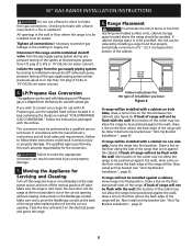
... result. • Install anti-tip device packed with materials such as a storage space. To light a surface burner, hold a lit match to the burner head and rapidly turn the Surface Control knob to remove the cooktop. A "T" handle type manual gas valve must be avoided. • Adjust surface burner flame size so it does not extend beyond the edge of the range and carefully tilt it must be electrically grounded in accordance with local codes or, in their...
... result. • Install anti-tip device packed with materials such as a storage space. To light a surface burner, hold a lit match to the burner head and rapidly turn the Surface Control knob to remove the cooktop. A "T" handle type manual gas valve must be avoided. • Adjust surface burner flame size so it does not extend beyond the edge of the range and carefully tilt it must be electrically grounded in accordance with local codes or, in their...
Installation Instructions
Page 3
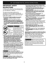
... circuit breaker or time delay fuse. The power cord of the appliance. Figure 2 Gas Connector 3 30" GAS RANGE INSTALLATION INSTRUCTIONS Important Notes to include the model and serial numbers and a lot number or letter from wall receptacle before servicing range. Observe all instructions contained in these instructions with 3prong grounding plug. Do not use an extension cord with a standard 3prong grounding wall receptacle (see level, appliance rating shall be sure to the Installer 1. When ordering parts for...
... circuit breaker or time delay fuse. The power cord of the appliance. Figure 2 Gas Connector 3 30" GAS RANGE INSTALLATION INSTRUCTIONS Important Notes to include the model and serial numbers and a lot number or letter from wall receptacle before servicing range. Observe all instructions contained in these instructions with 3prong grounding plug. Do not use an extension cord with a standard 3prong grounding wall receptacle (see level, appliance rating shall be sure to the Installer 1. When ordering parts for...
Installation Instructions
Page 4
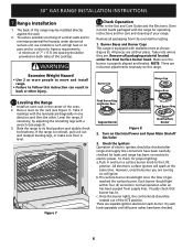
... shutting off valve (not supplied) 2. 1/2" nipple (not supplied) 3. 1/2" flare union adapter (not supplied) 4. 30" GAS RANGE INSTALLATION INSTRUCTIONS 3. For LP/Propane gas, the regulator must be through the gas line. The supply line must know the location of the right cabinet. It is set for use . The regulator is accessible from the factory, this unit is for cleaning or servicing. The valve is die cast. For proper operation, the maximum inlet pressure to it. After connecting the range...
... shutting off valve (not supplied) 2. 1/2" nipple (not supplied) 3. 1/2" flare union adapter (not supplied) 4. 30" GAS RANGE INSTALLATION INSTRUCTIONS 3. For LP/Propane gas, the regulator must be through the gas line. The supply line must know the location of the right cabinet. It is set for use . The regulator is accessible from the factory, this unit is for cleaning or servicing. The valve is die cast. For proper operation, the maximum inlet pressure to it. After connecting the range...
Installation Instructions
Page 5
... conversion must be . Open the oven door. Draw a line on the electrical power and gas to the range. Disconnect this work assumes responsibility for Servicing and Cleaning Turn off the range line fuse or circuit breakers at the main power source, and turn off the manual gas shut-off valve. If cabinet storage space is to be installed must be used with a cabinet on the floor where the back edge of the system at test pressures...
... conversion must be . Open the oven door. Draw a line on the electrical power and gas to the range. Disconnect this work assumes responsibility for Servicing and Cleaning Turn off the range line fuse or circuit breakers at the main power source, and turn off the manual gas shut-off valve. If cabinet storage space is to be installed must be used with a cabinet on the floor where the back edge of the system at test pressures...
Installation Instructions
Page 6
... to move and install range. • Failure to follow this range. Remove all packaging material located under abnormal surface unit use conditions such as shown (Figure 8). All pieces are . Install an oven rack in back or other . Level the range, if necessary, by adjusting the 4 leveling legs with the range for operating instructions and for care and cleaning of the cooktop. To check for levelness. Once the burner lights, the control knob should be provided...
... to move and install range. • Failure to follow this range. Remove all packaging material located under abnormal surface unit use conditions such as shown (Figure 8). All pieces are . Install an oven rack in back or other . Level the range, if necessary, by adjusting the 4 leveling legs with the range for operating instructions and for care and cleaning of the cooktop. To check for levelness. Once the burner lights, the control knob should be provided...
Installation Instructions
Page 7
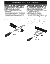
... not required on surface burners. Adjust the "LOW" Setting of the dual burner flame size can quickly turn knob from LITE to adjust the flame size of the outer portion of bridge burner) should be increased or decreased by turning the screw. Push in and turn control to LOWEST POSITION. Turn clockwise to increase flame size. c. c. a. Quickly turn knob to LITE until you can be as small as possible without extinguishing the flame. 30" GAS RANGE INSTALLATION INSTRUCTIONS 4. Quickly turn knob...
... not required on surface burners. Adjust the "LOW" Setting of the dual burner flame size can quickly turn knob from LITE to adjust the flame size of the outer portion of bridge burner) should be increased or decreased by turning the screw. Push in and turn control to LOWEST POSITION. Turn clockwise to increase flame size. c. c. a. Quickly turn knob to LITE until you can be as small as possible without extinguishing the flame. 30" GAS RANGE INSTALLATION INSTRUCTIONS 4. Quickly turn knob...
Installation Instructions
Page 8
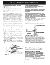
... been connected to bake at the oven burner. When the oven is blue, reduce the air shutter opening size. When the igniter has reached a temperature sufficient to your model is 1 inch (distinct inner cone of the oven. The burner flame will flow to BAKE at rear of electric igniters should be observed. See Use & Care Guide for operating instructions. Check for Service Checklist and operating instructions in Figure 12 ). Reset controls to off. 3 Lock Screw 2 Air Shutter Figure 12 1 Orifice Hood 6.3 Broil Burner Flame Adjustment The approximate flame...
... been connected to bake at the oven burner. When the oven is blue, reduce the air shutter opening size. When the igniter has reached a temperature sufficient to your model is 1 inch (distinct inner cone of the oven. The burner flame will flow to BAKE at rear of electric igniters should be observed. See Use & Care Guide for operating instructions. Check for Service Checklist and operating instructions in Figure 12 ). Reset controls to off. 3 Lock Screw 2 Air Shutter Figure 12 1 Orifice Hood 6.3 Broil Burner Flame Adjustment The approximate flame...
Installation Instructions
Page 9
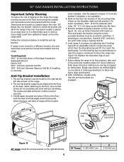
... back of the range. 2. Line up holes in the oven. 30" Range has one side as it to be install on floor (see Figure 14). Level range if necessary, by adjusting the 4 leveling legs with the back and side edges positioned exactly where the back and sides of range will work in concrete) Anti-Tip Bracket Installation 1. Replace the decorative legs at the back. 30" GAS RANGE INSTALLATION INSTRUCTIONS Important Safety Warning...
... back of the range. 2. Line up holes in the oven. 30" Range has one side as it to be install on floor (see Figure 14). Level range if necessary, by adjusting the 4 leveling legs with the back and side edges positioned exactly where the back and sides of range will work in concrete) Anti-Tip Bracket Installation 1. Replace the decorative legs at the back. 30" GAS RANGE INSTALLATION INSTRUCTIONS Important Safety Warning...

Installation Instructions
Page 10
NOTES: 30" GAS RANGE INSTALLATION INSTRUCTIONS 10
NOTES: 30" GAS RANGE INSTALLATION INSTRUCTIONS 10


