
User Manual
Page 2
... the setup screen may appear slightly different from time to time in the contents hereof without the obligation to the user manual on the CD-ROM. Add: No. 3, Wu-Chuan 3rd Rd., Wu-Ku Industrial Park, New Taipei City, Taiwan Tel: +886-2-77396888 Email: sales@edimax.com.tw 1 Should the programs prove defective following their respective holders. all necessary servicing, repair...
... the setup screen may appear slightly different from time to time in the contents hereof without the obligation to the user manual on the CD-ROM. Add: No. 3, Wu-Chuan 3rd Rd., Wu-Ku Industrial Park, New Taipei City, Taiwan Tel: +886-2-77396888 Email: sales@edimax.com.tw 1 Should the programs prove defective following their respective holders. all necessary servicing, repair...
User Manual
Page 3
... Chapter 1: Introduction ...3 1.1 Product Features...3 1.2 Application ...3 1.3 Compatibility...4 1.4 System Requirements ...4 Chapter 2: Interfaces ...5 2.1 LEDs...5 2.2 Button ...6 2.3 Gigabit Ethernet Port ...6 Chapter 3:Utility Software Installation ...7 3.1 Win 8 ...7 3.2 Win XP/Vista / 7 ...14 Chapter 4: Using the Utility Software ...20 4.1 Main Tab ...20 4.2 Diagnostics Tab ...21 4.3 About Tab...22 Chapter 5: Group Button ...23 5.1 Forming a HomePlug AV Logical Network 23 5.2 Joining a Network ...24 5.3 Leaving a Network & Joining another Network 25 Chapter 6: Troubleshooting ...26 2
... Chapter 1: Introduction ...3 1.1 Product Features...3 1.2 Application ...3 1.3 Compatibility...4 1.4 System Requirements ...4 Chapter 2: Interfaces ...5 2.1 LEDs...5 2.2 Button ...6 2.3 Gigabit Ethernet Port ...6 Chapter 3:Utility Software Installation ...7 3.1 Win 8 ...7 3.2 Win XP/Vista / 7 ...14 Chapter 4: Using the Utility Software ...20 4.1 Main Tab ...20 4.2 Diagnostics Tab ...21 4.3 About Tab...22 Chapter 5: Group Button ...23 5.1 Forming a HomePlug AV Logical Network 23 5.2 Joining a Network ...24 5.3 Leaving a Network & Joining another Network 25 Chapter 6: Troubleshooting ...26 2
User Manual
Page 4
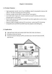
... • High-speed data transfer rate of up to 600Mbps, ideal for bandwidth-intensive HD video or 3D video streaming and online gaming • Features energy saving mode to reduce power consumption • Up to 300-meter range over a home's electrical circuit for better ...applications such as voice, video and online games • Supports IGMP managed multicast IP transmission, optimizing IPTV streaming • Compatible with all AV500 & AV200 Powerline adapters (HomePlug AV) 1.2 Application High-definition (HD) and standard-definition (SD) video distribution Broadband ...
... • High-speed data transfer rate of up to 600Mbps, ideal for bandwidth-intensive HD video or 3D video streaming and online gaming • Features energy saving mode to reduce power consumption • Up to 300-meter range over a home's electrical circuit for better ...applications such as voice, video and online games • Supports IGMP managed multicast IP transmission, optimizing IPTV streaming • Compatible with all AV500 & AV200 Powerline adapters (HomePlug AV) 1.2 Application High-definition (HD) and standard-definition (SD) video distribution Broadband ...
User Manual
Page 5
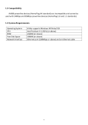
1.3 Compatibility AV600 powerline devices (HomePlug AV standard) are incompatible and cannot be used with 14Mbps and 85Mbps powerline devices (HomePlug 1.0 and 1.1 standards). 1.4 System Requirements Operating System CPU RAM Free Disk Space Network Interface Utility supports Windows XP/Vista/7/8 Intel Pentium III 1.0GHz (or above) 256MB (or above) 100MB (or above) Ethernet port (100Mbps or above) and an Ethernet cable 4
1.3 Compatibility AV600 powerline devices (HomePlug AV standard) are incompatible and cannot be used with 14Mbps and 85Mbps powerline devices (HomePlug 1.0 and 1.1 standards). 1.4 System Requirements Operating System CPU RAM Free Disk Space Network Interface Utility supports Windows XP/Vista/7/8 Intel Pentium III 1.0GHz (or above) 256MB (or above) 100MB (or above) Ethernet port (100Mbps or above) and an Ethernet cable 4
User Manual
Page 6
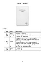
No other PLC device detected Powered on and the green indicator turns blinks quickly to indicate data is detecting a powerline link. The green indicator turns on Powered off 5 Chapter 2: Interfaces 2.1 LEDs LED Status Green LAN Blinking Off Green PLC Off Green PWR Off Description LAN port connected LAN activity (transferring data) LAN port not connected The green indicator turns on and the green indicator turns blinks slowly when the device is being transferred over the powerline link.
No other PLC device detected Powered on and the green indicator turns blinks quickly to indicate data is detecting a powerline link. The green indicator turns on Powered off 5 Chapter 2: Interfaces 2.1 LEDs LED Status Green LAN Blinking Off Green PLC Off Green PWR Off Description LAN port connected LAN activity (transferring data) LAN port not connected The green indicator turns on and the green indicator turns blinks slowly when the device is being transferred over the powerline link.
User Manual
Page 7
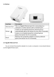
2.2 Button Interface Ethernet Port Group Reset Description This is a Gigabit Ethernet port for connecting to a router, a computer, or any network device via this Gigabit Ethernet port. 6 Leaves an encrypted powerline network group (press the button for less than 3 seconds). Restores the powerline adapter to factory defaults (press the button for 8~12 seconds). 2.3 Gigabit Ethernet Port You can connect the powerline adapter to a computer or other devices with a network port. Creates an encrypted powerline network group automatically (press the button for 8~12 seconds).
2.2 Button Interface Ethernet Port Group Reset Description This is a Gigabit Ethernet port for connecting to a router, a computer, or any network device via this Gigabit Ethernet port. 6 Leaves an encrypted powerline network group (press the button for less than 3 seconds). Restores the powerline adapter to factory defaults (press the button for 8~12 seconds). 2.3 Gigabit Ethernet Port You can connect the powerline adapter to a computer or other devices with a network port. Creates an encrypted powerline network group automatically (press the button for 8~12 seconds).
User Manual
Page 8
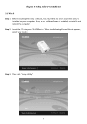
Chapter 3:Utility Software Installation 3.1 Win 8 Step 1 Before installing the utility software, make sure that no other utility software is installed on your CD-ROM drive. Step 3 Then click "Setup Utility". 7 Step 2 Insert the CD into your computer. If any other powerline utility is installed, uninstall it and reboot the computer. When the following EZmax Wizard appears, select your model.
Chapter 3:Utility Software Installation 3.1 Win 8 Step 1 Before installing the utility software, make sure that no other utility software is installed on your CD-ROM drive. Step 3 Then click "Setup Utility". 7 Step 2 Insert the CD into your computer. If any other powerline utility is installed, uninstall it and reboot the computer. When the following EZmax Wizard appears, select your model.
User Manual
Page 9
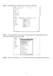
Step 5 Click Compatibility tab and check "Run this program in compatibility mode for:", then select Windows 7, then click "Apply". Step 4 Click right button on WinPCap4.1.2 then click "Properties". Step 6 Then click "WinPcap_4_1_2". The wizard will guide you through the setup process. 8
Step 5 Click Compatibility tab and check "Run this program in compatibility mode for:", then select Windows 7, then click "Apply". Step 4 Click right button on WinPCap4.1.2 then click "Properties". Step 6 Then click "WinPcap_4_1_2". The wizard will guide you through the setup process. 8
User Manual
Page 14
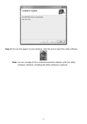
Note: You can manage all the connected powerline adapters with the utility software. However, installing the utility software is optional. 13 Click the icon to open the utility software. Step 12 An icon will appear on your desktop.
Note: You can manage all the connected powerline adapters with the utility software. However, installing the utility software is optional. 13 Click the icon to open the utility software. Step 12 An icon will appear on your desktop.

User Manual
Page 15
Step 2 Insert the CD into your model. Step 3 Then click "Setup Utility". 14 When the following EZmax Wizard appears, select your CD-ROM drive. If any other powerline utility is installed, uninstall it and reboot the computer. 3.2 Win XP/Vista / 7 Step 1 Before installing the utility software, make sure that no other utility software is installed on your computer.
Step 2 Insert the CD into your model. Step 3 Then click "Setup Utility". 14 When the following EZmax Wizard appears, select your CD-ROM drive. If any other powerline utility is installed, uninstall it and reboot the computer. 3.2 Win XP/Vista / 7 Step 1 Before installing the utility software, make sure that no other utility software is installed on your computer.
User Manual
Page 16
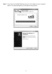
Step 4 If you through the setup process. 15 The wizard will guide you have not installed WinPcap version 4.1.2 (or higher) on your computer before.
Step 4 If you through the setup process. 15 The wizard will guide you have not installed WinPcap version 4.1.2 (or higher) on your computer before.
User Manual
Page 18
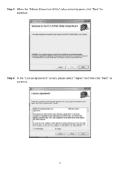
Step 5 When the "Edimax PowerLine Utility" setup wizard appears, click "Next" to continue. 17 Step 6 In the "License Agreement" screen, please select "I Agree" and then click "Next" to continue.
Step 5 When the "Edimax PowerLine Utility" setup wizard appears, click "Next" to continue. 17 Step 6 In the "License Agreement" screen, please select "I Agree" and then click "Next" to continue.
User Manual
Page 20
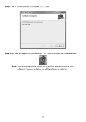
Step 10 An icon will appear on your desktop. Click the icon to open the utility software. Note: You can manage all the connected powerline adapters with the utility software. However, installing the utility software is complete, click "Close". Step 9 After the installation is optional. 19
Step 10 An icon will appear on your desktop. Click the icon to open the utility software. Note: You can manage all the connected powerline adapters with the utility software. However, installing the utility software is complete, click "Close". Step 9 After the installation is optional. 19
User Manual
Page 21
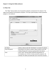
... powerline adapters in the network. Set Name Enter Password Scan Select a device and click "Set Name" to the network. The upper panel displays local powerline adapters. By default, this column is blank. By default, the utility automatically scans every few seconds. 20 Chapter 4: Using the Utility Software 4.1 Main Tab The "Main" tab provides a list of other remote powerline adapters. Click "Scan" and the utility software will perform an immediate scan of powerline adapters connected...
... powerline adapters in the network. Set Name Enter Password Scan Select a device and click "Set Name" to the network. The upper panel displays local powerline adapters. By default, this column is blank. By default, the utility automatically scans every few seconds. 20 Chapter 4: Using the Utility Software 4.1 Main Tab The "Main" tab provides a list of other remote powerline adapters. Click "Scan" and the utility software will perform an immediate scan of powerline adapters connected...
User Manual
Page 22
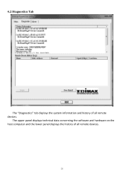
4.2 Diagnostics Tab The "Diagnostics" tab displays the system information and history of all remote devices. The upper panel displays technical data concerning the software and hardware on the host computer and the lower panel displays the history of all remote devices. 21
4.2 Diagnostics Tab The "Diagnostics" tab displays the system information and history of all remote devices. The upper panel displays technical data concerning the software and hardware on the host computer and the lower panel displays the history of all remote devices. 21
User Manual
Page 24
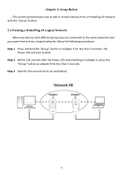
..." button. 5.1 Forming a HomePlug AV Logical Network When two devices with different group keys are connected to the same powerline and you want them to form a logical network, follow the following procedures: Step 1 Press and hold the "Group" button on adapter B for less than 3 seconds. Step 2 Within 120 seconds after the Power LED starts blinking on adapter A, press the "Group" button on adapter A for the connection to blink.
..." button. 5.1 Forming a HomePlug AV Logical Network When two devices with different group keys are connected to the same powerline and you want them to form a logical network, follow the following procedures: Step 1 Press and hold the "Group" button on adapter B for less than 3 seconds. Step 2 Within 120 seconds after the Power LED starts blinking on adapter A, press the "Group" button on adapter A for the connection to blink.
User Manual
Page 25
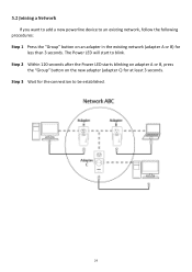
Step 3 Wait for the connection to blink. Step 2 Within 120 seconds after the Power LED starts blinking on adapter A or B, press the "Group" button on an adapter in the existing network (adapter A or B) for less than 3 seconds. The Power LED will start to be established. 24 5.2 Joining a Network If you want to add a new powerline device to an existing network, follow the following procedures: Step 1 Press the "Group" button on the new adapter (adapter C) for at least 3 seconds.
Step 3 Wait for the connection to blink. Step 2 Within 120 seconds after the Power LED starts blinking on adapter A or B, press the "Group" button on an adapter in the existing network (adapter A or B) for less than 3 seconds. The Power LED will start to be established. 24 5.2 Joining a Network If you want to add a new powerline device to an existing network, follow the following procedures: Step 1 Press the "Group" button on the new adapter (adapter C) for at least 3 seconds.
User Manual
Page 26
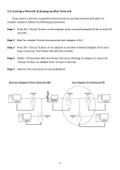
... Power LED will start to blink. Step 4 Within 120 seconds after the Power LED starts blinking on adapter D, press the "Group" button on the adapter to be removed (adapter B) for at least 3 seconds. Step 5 Wait for the connection to be disconnected with adapter A & C. Step 2 Wait for adapter B to be established. 25 5.3 Leaving a Network & Joining another Network If you want to remove a powerline device from an existing network and add it...
... Power LED will start to blink. Step 4 Within 120 seconds after the Power LED starts blinking on adapter D, press the "Group" button on the adapter to be removed (adapter B) for at least 3 seconds. Step 5 Wait for the connection to be disconnected with adapter A & C. Step 2 Wait for adapter B to be established. 25 5.3 Leaving a Network & Joining another Network If you want to remove a powerline device from an existing network and add it...
User Manual
Page 27
... a connection across different circuit breaker boxes. Using a power strip or surge protector may not be able to establish a connection across different circuit breaker boxes by unplugging it from the electric outlet for 2 seconds on GFI protected electric outlets, as some outlets will reset and attempt to connect. Chapter 6: Troubleshooting If your powerline adapters may degrade network performance or completely block network signals. This powerline adapter should not be used in again. Use a pin to hold the reset button...
... a connection across different circuit breaker boxes. Using a power strip or surge protector may not be able to establish a connection across different circuit breaker boxes by unplugging it from the electric outlet for 2 seconds on GFI protected electric outlets, as some outlets will reset and attempt to connect. Chapter 6: Troubleshooting If your powerline adapters may degrade network performance or completely block network signals. This powerline adapter should not be used in again. Use a pin to hold the reset button...
User Manual
Page 28
... United Kingdom. Operation is connected. 4. Safety This equipment is intended for certification. Use in the application for home and office use with electrical equipment. This transmitter is not authorized. Connect the equipment into an outlet on radio equipment and telecommunication terminal equipment and the mutual recognition of electric shock and static electricity when working with the specific antenna tested...
... United Kingdom. Operation is connected. 4. Safety This equipment is intended for certification. Use in the application for home and office use with electrical equipment. This transmitter is not authorized. Connect the equipment into an outlet on radio equipment and telecommunication terminal equipment and the mutual recognition of electric shock and static electricity when working with the specific antenna tested...


