
Datasheet
Page 1
...; Easy plug-n-play setup and 128 bit AES security • Maximum powerline speed of network resources. Product specifications and design are subject to 500Mbps. So even when the HP-5102AC is built with 200Mbps powerline adapters • Features energy saving mode to reduce power consumption • Utilizes existing electrical wires to transmit network data • Powerline transmission range up to change without notice. if your home or...
...; Easy plug-n-play setup and 128 bit AES security • Maximum powerline speed of network resources. Product specifications and design are subject to 500Mbps. So even when the HP-5102AC is built with 200Mbps powerline adapters • Features energy saving mode to reduce power consumption • Utilizes existing electrical wires to transmit network data • Powerline transmission range up to change without notice. if your home or...
Datasheet
Page 2
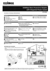
... AES link encryption with key management Dimensions & Weight 102 x 64 x 43mm 184g Certification CE, FCC, LVD Operating Range Up to 300 meters IGMP Support for IPv4/IGMPv1,v2,v3 snooping Support for IPv6 and MLDv1, v2 snooping Max 16 source addresses and group members Temperature & Humidity 0-45 degrees Celsius 10-90% (non-condensing) Power Consumption 4W NETWORK SETUP DIAGRAM • Plug a HP-5102AC into a power outlet and connect...
... AES link encryption with key management Dimensions & Weight 102 x 64 x 43mm 184g Certification CE, FCC, LVD Operating Range Up to 300 meters IGMP Support for IPv4/IGMPv1,v2,v3 snooping Support for IPv6 and MLDv1, v2 snooping Max 16 source addresses and group members Temperature & Humidity 0-45 degrees Celsius 10-90% (non-condensing) Power Consumption 4W NETWORK SETUP DIAGRAM • Plug a HP-5102AC into a power outlet and connect...

Manual
Page 2
... to the contents hereof and specifically disclaims any warranties, merchantability, or fitness for updates. Add: No. 3, Wu-Chuan 3rd Rd., Wu-Ku Industrial Park, New Taipei City, Taiwan Tel: +886-2-77396888 Email: sales@edimax.com.tw 1 Edimax Technology Co., Ltd. Edimax Technology Co., Ltd. Should the programs prove defective following their respective holders. all necessary servicing, repair, and any incidental or consequential...
... to the contents hereof and specifically disclaims any warranties, merchantability, or fitness for updates. Add: No. 3, Wu-Chuan 3rd Rd., Wu-Ku Industrial Park, New Taipei City, Taiwan Tel: +886-2-77396888 Email: sales@edimax.com.tw 1 Edimax Technology Co., Ltd. Edimax Technology Co., Ltd. Should the programs prove defective following their respective holders. all necessary servicing, repair, and any incidental or consequential...

Manual
Page 3
... ...3 1.1 Product Features...3 1.2 Application ...3 1.3 Compatibility...4 1.4 System Requirements ...4 Chapter 2: About the Product...5 2.1 LED Definitions...5 2.2 Interface...6 2.3 Fast Ethernet Port ...6 Chapter 3:Utility Software Installation ...7 3.1 Win 8 ...7 3.2 Win XP/Vista / 7 ...15 Chapter 4: Using the Utility Software ...21 4.1 Main Tab ...21 4.2 Diagnostics Tab ...22 4.3 About Tab...23 Chapter 5: Group Button ...24 5.1 Forming a HomePlug AV Logical Network 24 5.2 Joining a Network ...25 5.3 Leaving a Network & Joining another Network 26 Chapter 6: Troubleshooting ...27 2
... ...3 1.1 Product Features...3 1.2 Application ...3 1.3 Compatibility...4 1.4 System Requirements ...4 Chapter 2: About the Product...5 2.1 LED Definitions...5 2.2 Interface...6 2.3 Fast Ethernet Port ...6 Chapter 3:Utility Software Installation ...7 3.1 Win 8 ...7 3.2 Win XP/Vista / 7 ...15 Chapter 4: Using the Utility Software ...21 4.1 Main Tab ...21 4.2 Diagnostics Tab ...22 4.3 About Tab...23 Chapter 5: Group Button ...24 5.1 Forming a HomePlug AV Logical Network 24 5.2 Joining a Network ...25 5.3 Leaving a Network & Joining another Network 26 Chapter 6: Troubleshooting ...27 2
Manual
Page 4
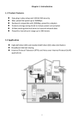
... power consumption Utilizes existing electrical wires to transmit network data Powerline transmission range up to 300 meters 1.2 Application High-definition (HD) and standard-definition (SD) video distribution Broadband Internet sharing Internet Protocol Television (IPTV) and Voice over Internet Protocol (VoIP) applications 3 Chapter 1: Introduction 1.1 Product Features Easy plug-n-play setup and 128-bit AES security Max...
... power consumption Utilizes existing electrical wires to transmit network data Powerline transmission range up to 300 meters 1.2 Application High-definition (HD) and standard-definition (SD) video distribution Broadband Internet sharing Internet Protocol Television (IPTV) and Voice over Internet Protocol (VoIP) applications 3 Chapter 1: Introduction 1.1 Product Features Easy plug-n-play setup and 128-bit AES security Max...
Manual
Page 5
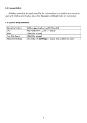
1.3 Compatibility 500Mbps powerline devices (HomePlug AV standard) are incompatible and cannot be used with 14Mbps and 85Mbps powerline devices (HomePlug 1.0 and 1.1 standards). 1.4 System Requirements Operating System CPU RAM Free Disk Space Network Interface Utility supports Windows XP/Vista/7/8 Intel Pentium III 1.0GHz (or above) 256MB (or above) 100MB (or above) Ethernet port (100Mbps or above) and an Ethernet cable 4
1.3 Compatibility 500Mbps powerline devices (HomePlug AV standard) are incompatible and cannot be used with 14Mbps and 85Mbps powerline devices (HomePlug 1.0 and 1.1 standards). 1.4 System Requirements Operating System CPU RAM Free Disk Space Network Interface Utility supports Windows XP/Vista/7/8 Intel Pentium III 1.0GHz (or above) 256MB (or above) 100MB (or above) Ethernet port (100Mbps or above) and an Ethernet cable 4

Manual
Page 6
... every 15 seconds. 5 2.1 LED Definitions Chapter 2: About the Product LED Status Description Green LAN port connected LAN Blinking Off LAN activity (transferring data) LAN port not connected The green indicator turns on and the yellow indicator blinks slowly when the device is being transferred over the powerline link. The green indicator turns on and the yellow indicator PLC blinks quickly to indicate data is detecting a Green/Yellow powerline link.
... every 15 seconds. 5 2.1 LED Definitions Chapter 2: About the Product LED Status Description Green LAN port connected LAN Blinking Off LAN activity (transferring data) LAN port not connected The green indicator turns on and the yellow indicator blinks slowly when the device is being transferred over the powerline link. The green indicator turns on and the yellow indicator PLC blinks quickly to indicate data is detecting a Green/Yellow powerline link.

Manual
Page 7
Restores the powerline adapter to factory defaults (press the button for connecting to a computer or other devices with a network port. This is a Fast Ethernet port for 10~15 seconds). 2.3 Fast Ethernet Port You can connect the powerline adapter to the adapter, just as a normal wall socket would. Creates an encrypted powerline network group automatically (press the button for 5~8 seconds). 2.2 Interface Interface Integrated Power Socket Ethernet Port Group/Reset Description The integrated electrical socket...
Restores the powerline adapter to factory defaults (press the button for connecting to a computer or other devices with a network port. This is a Fast Ethernet port for 10~15 seconds). 2.3 Fast Ethernet Port You can connect the powerline adapter to the adapter, just as a normal wall socket would. Creates an encrypted powerline network group automatically (press the button for 5~8 seconds). 2.2 Interface Interface Integrated Power Socket Ethernet Port Group/Reset Description The integrated electrical socket...
Manual
Page 8
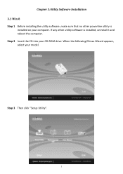
When the following EZmax Wizard appears, select your CD-ROM drive. Step 2 Insert the CD into your model. If any other powerline utility is installed, uninstall it and reboot the computer. Chapter 3:Utility Software Installation 3.1 Win 8 Step 1 Before installing the utility software, make sure that no other utility software is installed on your computer. Step 3 Then click "Setup Utility". 7
When the following EZmax Wizard appears, select your CD-ROM drive. Step 2 Insert the CD into your model. If any other powerline utility is installed, uninstall it and reboot the computer. Chapter 3:Utility Software Installation 3.1 Win 8 Step 1 Before installing the utility software, make sure that no other utility software is installed on your computer. Step 3 Then click "Setup Utility". 7
Manual
Page 13
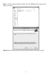
Step 9 Click the "Edimax PowerLine Utility", the "PLC 500Mbps Utility" appears, click "Next" to install the utility software, and then click "Next". 12 Step 10 Select where you want to continue.
Step 9 Click the "Edimax PowerLine Utility", the "PLC 500Mbps Utility" appears, click "Next" to install the utility software, and then click "Next". 12 Step 10 Select where you want to continue.

Manual
Page 15
Click the icon to open the utility software. However, installing the utility software is optional. 14 Note: You can manage all the connected powerline adapters with the utility software. Step 12 An icon will appear on your desktop.
Click the icon to open the utility software. However, installing the utility software is optional. 14 Note: You can manage all the connected powerline adapters with the utility software. Step 12 An icon will appear on your desktop.
Manual
Page 16
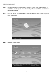
Step 2 Insert the CD into your model. When the following EZmax Wizard appears, select your CD-ROM drive. Step 3 Then click "Setup Utility". 15 If any other powerline utility is installed, uninstall it and reboot the computer. 3.2 Win XP/Vista / 7 Step 1 Before installing the utility software, make sure that no other utility software is installed on your computer.
Step 2 Insert the CD into your model. When the following EZmax Wizard appears, select your CD-ROM drive. Step 3 Then click "Setup Utility". 15 If any other powerline utility is installed, uninstall it and reboot the computer. 3.2 Win XP/Vista / 7 Step 1 Before installing the utility software, make sure that no other utility software is installed on your computer.
Manual
Page 19
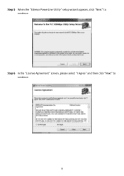
Step 5 When the "Edimax PowerLine Utility" setup wizard appears, click "Next" to continue. 18 Step 6 In the "License Agreement" screen, please select "I Agree" and then click "Next" to continue.
Step 5 When the "Edimax PowerLine Utility" setup wizard appears, click "Next" to continue. 18 Step 6 In the "License Agreement" screen, please select "I Agree" and then click "Next" to continue.

Manual
Page 21
However, installing the utility software is complete, click "Close". Step 10 An icon will appear on your desktop. Click the icon to open the utility software. Step 9 After the installation is optional. 20 Note: You can manage all the connected powerline adapters with the utility software.
However, installing the utility software is complete, click "Close". Step 10 An icon will appear on your desktop. Click the icon to open the utility software. Step 9 After the installation is optional. 20 Note: You can manage all the connected powerline adapters with the utility software.
Manual
Page 22
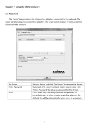
... lower panel displays remote powerline adapters in the network. Click "Scan" and the utility software will perform an immediate scan of powerline adapters connected to the network. Chapter 4: Using the Utility Software 4.1 Main Tab The "Main" tab provides a list of other remote powerline adapters. By default, this column is blank. Set Name Enter Password Scan Select a device and click "Set Name" to set up a password for the device. The upper panel displays local powerline adapters.
... lower panel displays remote powerline adapters in the network. Click "Scan" and the utility software will perform an immediate scan of powerline adapters connected to the network. Chapter 4: Using the Utility Software 4.1 Main Tab The "Main" tab provides a list of other remote powerline adapters. By default, this column is blank. Set Name Enter Password Scan Select a device and click "Set Name" to set up a password for the device. The upper panel displays local powerline adapters.

Manual
Page 25
... how to add or remove devices from a HomePlug AV network with the "Group" button. 5.1 Forming a HomePlug AV Logical Network When two devices with different group keys are connected to the same powerline and you want them to form a logical network, follow the following procedures: Step 1 Press and hold the "Group" button on adapter B for the connection to blink. The Power LED will start to be...
... how to add or remove devices from a HomePlug AV network with the "Group" button. 5.1 Forming a HomePlug AV Logical Network When two devices with different group keys are connected to the same powerline and you want them to form a logical network, follow the following procedures: Step 1 Press and hold the "Group" button on adapter B for the connection to blink. The Power LED will start to be...

Manual
Page 26
5.2 Joining a Network If you want to add a new powerline device to an existing network, follow the following procedures: Step 1 Press the "Group" button on the new adapter (adapter C) for at least 3 seconds. The Power LED will start to be established. 25 Step 3 Wait for less than 3 seconds. Step 2 Within 120 seconds after the Power LED starts blinking on adapter A or B, press the "Group" button on an adapter in the existing network (adapter A or B) for the connection to blink.
5.2 Joining a Network If you want to add a new powerline device to an existing network, follow the following procedures: Step 1 Press the "Group" button on the new adapter (adapter C) for at least 3 seconds. The Power LED will start to be established. 25 Step 3 Wait for less than 3 seconds. Step 2 Within 120 seconds after the Power LED starts blinking on adapter A or B, press the "Group" button on an adapter in the existing network (adapter A or B) for the connection to blink.

Manual
Page 27
Step 2 Wait for the connection to be established. 26 Step 5 Wait for adapter B to be disconnected with adapter A & C. The Power LED will start to blink. Step 4 Within 120 seconds after the Power LED starts blinking on adapter D, press the "Group" button on adapter B for at least 3 seconds. 5.3 Leaving a Network & Joining another Network If you want to remove a powerline device from an existing network and add it to another network (adapter D) for less...
Step 2 Wait for the connection to be established. 26 Step 5 Wait for adapter B to be disconnected with adapter A & C. The Power LED will start to blink. Step 4 Within 120 seconds after the Power LED starts blinking on adapter D, press the "Group" button on adapter B for at least 3 seconds. 5.3 Leaving a Network & Joining another Network If you want to remove a powerline device from an existing network and add it to another network (adapter D) for less...
Manual
Page 28
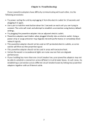
... reset button down for 2 seconds on GFI protected electric outlets, as some outlets will reset and attempt to establish a connection across different circuit breaker boxes by unplugging it from the electric outlet for 10 seconds and plugging it in areas with excessive heat. Certain florescent or incandescent lights are trying to connect. Using a power strip or surge protector may not be able to establish a connection using factory default settings. Try plugging the powerline adapter...
... reset button down for 2 seconds on GFI protected electric outlets, as some outlets will reset and attempt to establish a connection across different circuit breaker boxes by unplugging it from the electric outlet for 10 seconds and plugging it in areas with excessive heat. Certain florescent or incandescent lights are trying to connect. Using a power strip or surge protector may not be able to establish a connection using factory default settings. Try plugging the powerline adapter...
Manual
Page 29
... used for this device is restricted for an uncontrolled environment. All guidelines of this device may cause harmful interference to Part 15 of exceeding the FCC radio frequency exposure limits, human proximity to operate equipment. EU Countries Not Intended for help. Any changes...cause undesired operation. The ETSI version of those who install and use it. FCC Caution This device and its antenna must not be co-located or operating in conjunction with the specific antenna tested in the laptop computer(s) configurations with PCMCIA slot on , the user is connected. 4....
... used for this device is restricted for an uncontrolled environment. All guidelines of this device may cause harmful interference to Part 15 of exceeding the FCC radio frequency exposure limits, human proximity to operate equipment. EU Countries Not Intended for help. Any changes...cause undesired operation. The ETSI version of those who install and use it. FCC Caution This device and its antenna must not be co-located or operating in conjunction with the specific antenna tested in the laptop computer(s) configurations with PCMCIA slot on , the user is connected. 4....


