
User Manual
Page 2
.... The software and specifications are trademarks and/or registered trademarks of all rights reserved. No part of such revision or changes. For more information about this manual are subject to the contents hereof and specifically disclaims any person of this manual is sold or licensed as is. Copyright Copyright Edimax Technology Co., Ltd. makes no representations or warranties...
.... The software and specifications are trademarks and/or registered trademarks of all rights reserved. No part of such revision or changes. For more information about this manual are subject to the contents hereof and specifically disclaims any person of this manual is sold or licensed as is. Copyright Copyright Edimax Technology Co., Ltd. makes no representations or warranties...
User Manual
Page 3
Contents Chapter 1: Introduction ...3 1.1 Product Features...3 1.2 Application ...3 1.3 Compatibility...3 1.4 System Requirements ...4 Chapter 2: Adapter ...5 2.1 Ethernet Port...5 2.2 Buttons...5 2.3 LEDs...6 Chapter 3: Utility Software Installation ...7 Chapter 4: Using the Utility Software ...14 4.1 Main Tab ...14 4.2 Privacy Tab ...15 4.3 Diagnostics Tab ...16 4.4 About Tab...17 Chapter 5: Security (Group) Button...18 5.1 Forming a HomePlug AV Logical Network 18 5.2 Joining a Network ...18 5.3 Leaving a Network ...19 2
Contents Chapter 1: Introduction ...3 1.1 Product Features...3 1.2 Application ...3 1.3 Compatibility...3 1.4 System Requirements ...4 Chapter 2: Adapter ...5 2.1 Ethernet Port...5 2.2 Buttons...5 2.3 LEDs...6 Chapter 3: Utility Software Installation ...7 Chapter 4: Using the Utility Software ...14 4.1 Main Tab ...14 4.2 Privacy Tab ...15 4.3 Diagnostics Tab ...16 4.4 About Tab...17 Chapter 5: Security (Group) Button...18 5.1 Forming a HomePlug AV Logical Network 18 5.2 Joining a Network ...18 5.3 Leaving a Network ...19 2
User Manual
Page 4
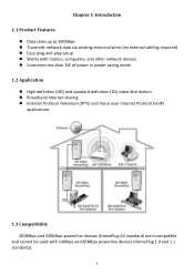
Chapter 1: Introduction 1.1 Product Features Data rates up to 500Mbps Transmits network data via existing electrical wires (no external cabling required) Easy plug-and-play setup Works with routers, computers, and other network devices Consumes less than 1W of power in power saving mode 1.2 Application High-definition (HD) and standard-definition (SD) video distribution Broadband Internet sharing ...
Chapter 1: Introduction 1.1 Product Features Data rates up to 500Mbps Transmits network data via existing electrical wires (no external cabling required) Easy plug-and-play setup Works with routers, computers, and other network devices Consumes less than 1W of power in power saving mode 1.2 Application High-definition (HD) and standard-definition (SD) video distribution Broadband Internet sharing ...
User Manual
Page 6
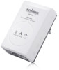
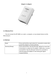
Press and hold the "Security (Group)" button for 3 seconds to add the powerline adapter to the existing AV logical network (AVLN). 5 or press and hold the "Security (Group)" button for more than 10 seconds to factory defaults. Chapter 2: Adapter 2.1 Ethernet Port You can connect the HP-5001 to a router, a computer, or any network device via this Ethernet port. 2.2 Buttons Reset Security (Group) Press and hold the reset button for 3 seconds to restore the powerline adapter to randomize the adapter's NMK value;
Press and hold the "Security (Group)" button for 3 seconds to add the powerline adapter to the existing AV logical network (AVLN). 5 or press and hold the "Security (Group)" button for more than 10 seconds to factory defaults. Chapter 2: Adapter 2.1 Ethernet Port You can connect the HP-5001 to a router, a computer, or any network device via this Ethernet port. 2.2 Buttons Reset Security (Group) Press and hold the reset button for 3 seconds to restore the powerline adapter to randomize the adapter's NMK value;
User Manual
Page 7
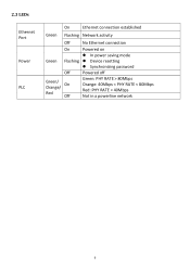
2.3 LEDs Ethernet Port Power PLC On Ethernet connection established Green Flashing Network activity Off No Ethernet connection On Powered on In power saving mode Green Flashing Device resetting Synchronizing password Off Powered off Green/ Orange/ On Red Off Green: PHY RATE > 80Mbps Orange: 40Mbps < PHY RATE < 80Mbps Red: PHY RATE < 40Mbps Not in a powerline network 6
2.3 LEDs Ethernet Port Power PLC On Ethernet connection established Green Flashing Network activity Off No Ethernet connection On Powered on In power saving mode Green Flashing Device resetting Synchronizing password Off Powered off Green/ Orange/ On Red Off Green: PHY RATE > 80Mbps Orange: 40Mbps < PHY RATE < 80Mbps Red: PHY RATE < 40Mbps Not in a powerline network 6
User Manual
Page 8
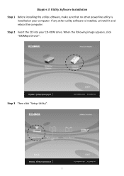
Step 3 Then click "Setup Utility". 7 If any other powerline utility is installed, uninstall it and reboot the computer. Step 2 Insert the CD into your computer. When the following image appears, click "500Mbps Device". Chapter 3: Utility Software Installation Step 1 Before installing the utility software, make sure that no other utility software is installed on your CD-ROM drive.
Step 3 Then click "Setup Utility". 7 If any other powerline utility is installed, uninstall it and reboot the computer. Step 2 Insert the CD into your computer. When the following image appears, click "500Mbps Device". Chapter 3: Utility Software Installation Step 1 Before installing the utility software, make sure that no other utility software is installed on your CD-ROM drive.

User Manual
Page 9
Note : You will get the following image, if your computer did not install WinPcap4.1.2 before. Please click "Apply" to install WinPcap4.1.2. 8
Note : You will get the following image, if your computer did not install WinPcap4.1.2 before. Please click "Apply" to install WinPcap4.1.2. 8
User Manual
Page 12
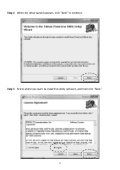
Step 5 Select where you want to continue. Step 4 When the setup wizard appears, click "Next" to install the utility software, and then click "Next". 11
Step 5 Select where you want to continue. Step 4 When the setup wizard appears, click "Next" to install the utility software, and then click "Next". 11
User Manual
Page 14
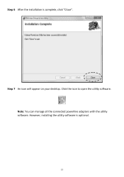
Click the icon to open the utility software. Step 6 After the installation is optional. 13 Step 7 An icon will appear on your desktop. However, installing the utility software is complete, click "Close". Note: You can manage all the connected powerline adapters with the utility software.
Click the icon to open the utility software. Step 6 After the installation is optional. 13 Step 7 An icon will appear on your desktop. However, installing the utility software is complete, click "Close". Note: You can manage all the connected powerline adapters with the utility software.
User Manual
Page 15
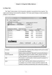
... local powerline adapters. This button is blank. Connect Rename Enter Password Add Scan Click "Connect" and the utility software will perform an immediate scan of powerline adapters connected to set up a password for other remote powerline adapters. Chapter 4: Using the Utility Software 4.1 Main Tab The "Main" tab provides a list of other local powerline adapters. The lower panel displays remote powerline adapters in the network. Select a device and click "Enter Password" to the computer. Click "Scan" and the utility software...
... local powerline adapters. This button is blank. Connect Rename Enter Password Add Scan Click "Connect" and the utility software will perform an immediate scan of powerline adapters connected to set up a password for other remote powerline adapters. Chapter 4: Using the Utility Software 4.1 Main Tab The "Main" tab provides a list of other local powerline adapters. The lower panel displays remote powerline adapters in the network. Select a device and click "Enter Password" to the computer. Click "Scan" and the utility software...
User Manual
Page 16
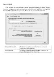
This button is used to change the network name and password of all devices that appear in the "Main" tab will be changed to "Private". Set Local Device Only Set All Devices This button is modified to anything other than the default, the network type in the "Main" tab. 15 If the network name is used to change the logical network of the local device. 4.2 Privacy Tab In the "Privacy" tab, you can create a private network by changing the default network name and configure its security settings.
This button is used to change the network name and password of all devices that appear in the "Main" tab will be changed to "Private". Set Local Device Only Set All Devices This button is modified to anything other than the default, the network type in the "Main" tab. 15 If the network name is used to change the logical network of the local device. 4.2 Privacy Tab In the "Privacy" tab, you can create a private network by changing the default network name and configure its security settings.
User Manual
Page 17
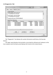
The upper panel displays technical data concerning the software and hardware on the host computer and the lower panel displays the history of all remote devices. 16 4.3 Diagnostics Tab The "Diagnostics" tab displays the system information and history of all remote devices.
The upper panel displays technical data concerning the software and hardware on the host computer and the lower panel displays the history of all remote devices. 16 4.3 Diagnostics Tab The "Diagnostics" tab displays the system information and history of all remote devices.
User Manual
Page 18
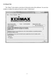
4.4 About Tab The "About" tab contains some basic information about the software. You can also enable or disable the autoscan function under "Preferences". 17
4.4 About Tab The "About" tab contains some basic information about the software. You can also enable or disable the autoscan function under "Preferences". 17
User Manual
Page 19
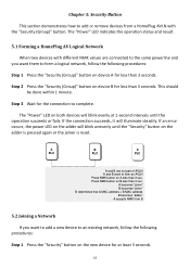
... is reset. A PLC B PLC C PLC A and B are connected to the same powerline and you want to add a new device to an existing network, follow the following procedures: Step 1 Press the "Security" button on the new device for less than 3 sec. A becomes "joiner" B becomes "joiner" B determines that A MAC address < B MAC address B becomes "adder" A accepts NMK from a HomePlug AVLN with different NMK values are not part...
... is reset. A PLC B PLC C PLC A and B are connected to the same powerline and you want to add a new device to an existing network, follow the following procedures: Step 1 Press the "Security" button on the new device for less than 3 sec. A becomes "joiner" B becomes "joiner" B determines that A MAC address < B MAC address B becomes "adder" A accepts NMK from a HomePlug AVLN with different NMK values are not part...

User Manual
Page 20
... B form an AVLN C wants to leave the AVLN Press NMK button on A more than 3 sec. Step 2 Press the "Security" button on any device in the network for the device to reset. If the connection succeeds, it will blink unevenly until the operation succeeds or fails. If an error occurs, the power LED on the adder will illuminate steadily if no...
... B form an AVLN C wants to leave the AVLN Press NMK button on A more than 3 sec. Step 2 Press the "Security" button on any device in the network for the device to reset. If the connection succeeds, it will blink unevenly until the operation succeeds or fails. If an error occurs, the power LED on the adder will illuminate steadily if no...
User Manual
Page 21
Connect the equipment into an outlet on a circuit different from that to which can be co-located or operating in conjunction with electrical equipment. Any changes or modifications not expressly approved by one or more of the ...operate equipment. Operation is also authorized for use with the limits for a Class B digital device, pursuant to Part 15 of electric shock and static electricity when working with any other devices such as tested in the application for certification, and can radiate radio frequency energy and, if not installed and used for Use The ETSI version...
Connect the equipment into an outlet on a circuit different from that to which can be co-located or operating in conjunction with electrical equipment. Any changes or modifications not expressly approved by one or more of the ...operate equipment. Operation is also authorized for use with the limits for a Class B digital device, pursuant to Part 15 of electric shock and static electricity when working with any other devices such as tested in the application for certification, and can radiate radio frequency energy and, if not installed and used for Use The ETSI version...


