User Guide
Page 4
Connecting IDE Hard Disk Drives 26 Connecting Serial ATA Cables 27 Connecting Internal Headers 28 Front Panel Header 28 USB Headers 29 Audio Header 30 Fan Connections 31 Expansion Slots 32 PCI-E x16 Slots 33 Onboard Buttons 35 Clear CMOS Button 35 RESET and POWER Button 35 Post Port Debug LED and LED Status Indicators 36 Post Port Debug LED 36 LED Status Indicators 36 Jumper Settings 37 PCI-E Disable Jumper 37 Voltage Measure Point 38 EVGA Control Panel (ECP 39 Configuring the BIOS 47 Enter BIOS Setup 48 Main Menu ...49 Standard BIOS FeaturesMenu 51 System Time/SystemDate...
Connecting IDE Hard Disk Drives 26 Connecting Serial ATA Cables 27 Connecting Internal Headers 28 Front Panel Header 28 USB Headers 29 Audio Header 30 Fan Connections 31 Expansion Slots 32 PCI-E x16 Slots 33 Onboard Buttons 35 Clear CMOS Button 35 RESET and POWER Button 35 Post Port Debug LED and LED Status Indicators 36 Post Port Debug LED 36 LED Status Indicators 36 Jumper Settings 37 PCI-E Disable Jumper 37 Voltage Measure Point 38 EVGA Control Panel (ECP 39 Configuring the BIOS 47 Enter BIOS Setup 48 Main Menu ...49 Standard BIOS FeaturesMenu 51 System Time/SystemDate...

User Guide
Page 5
EVGA Classified SR-2 Motherboard E-SATA Controller (Back panel 54 SATA Configuration...55 Advanced Chipset Features 56 USB Configuration 56 PCI-E Configuration 56 PCI/PNP Resource Management 58 Clear NVRAM...58 Plug & Play O/S...58 PCI Latency Timer 58 Allocate IRQ to PCI VGA 59 Pallette Snooping 59 PCI IDE Busmaster 59 Offboard PCI/ISA IDE Card 59 Boot Configuration Features 60 Boot Settings Configuration 60 Boot Device Priority 60 Hard Disk Drives 60 Power Management Features 61 ACPI Configuration 61 Hardware Health Configuration 62 H/W HealthFunction 62 CPU Fan Mode ...
EVGA Classified SR-2 Motherboard E-SATA Controller (Back panel 54 SATA Configuration...55 Advanced Chipset Features 56 USB Configuration 56 PCI-E Configuration 56 PCI/PNP Resource Management 58 Clear NVRAM...58 Plug & Play O/S...58 PCI Latency Timer 58 Allocate IRQ to PCI VGA 59 Pallette Snooping 59 PCI IDE Busmaster 59 Offboard PCI/ISA IDE Card 59 Boot Configuration Features 60 Boot Settings Configuration 60 Boot Device Priority 60 Hard Disk Drives 60 Power Management Features 61 ACPI Configuration 61 Hardware Health Configuration 62 H/W HealthFunction 62 CPU Fan Mode ...

User Guide
Page 7
Power Supply Connectors 24 Figure 4. Standard BIOS Features Menu 51 Figure 5. Advanced BIOS Features Menu 53 Figure 6. Advanced Chipset Features 56 Figure 8. PCI/PNP Resource Management 58 Figure 9. Boot Configuration Features 60 Figure 10. H/W Health Configuration 62 Figure 12. SATA Configuration 55 Figure 7. EVGA Classified SR-2 Motherboard Layout 15 Figure 2. Power Management Features 61 Figure 11. Frequency/Voltage Control 63 7 Chassis Back panel Connectors 16 Figure 3. EVGA Classified SR-2 Motherboard List of Figures Figure 1.
Power Supply Connectors 24 Figure 4. Standard BIOS Features Menu 51 Figure 5. Advanced BIOS Features Menu 53 Figure 6. Advanced Chipset Features 56 Figure 8. PCI/PNP Resource Management 58 Figure 9. Boot Configuration Features 60 Figure 10. H/W Health Configuration 62 Figure 12. SATA Configuration 55 Figure 7. EVGA Classified SR-2 Motherboard Layout 15 Figure 2. Power Management Features 61 Figure 11. Frequency/Voltage Control 63 7 Chassis Back panel Connectors 16 Figure 3. EVGA Classified SR-2 Motherboard List of Figures Figure 1.

User Guide
Page 10
... 64bit (64bit Recommended) Contains Intel 5520 and ICH10R chipset System Memory support Supports triple channel DDR3-1600+ (Overclocked). Supports up to 4.8Gbps transmission rate 10 Supports up to 48GBs DDR3 (ECC or Non ECC memory). USB 2.0 Ports Supports hot plug Ten USB 2.0 ports (six back panel ports, four onboard USB headers) Supports wake-up from S1 and S3 mode Supports USB 2.0 protocol up to 480 Mbps transmission rate Two USB 3.0 ports (Rear panel) Backwards compatible USB 2.0 and USB 3.0 support.
... 64bit (64bit Recommended) Contains Intel 5520 and ICH10R chipset System Memory support Supports triple channel DDR3-1600+ (Overclocked). Supports up to 4.8Gbps transmission rate 10 Supports up to 48GBs DDR3 (ECC or Non ECC memory). USB 2.0 Ports Supports hot plug Ten USB 2.0 ports (six back panel ports, four onboard USB headers) Supports wake-up from S1 and S3 mode Supports USB 2.0 protocol up to 480 Mbps transmission rate Two USB 3.0 ports (Rear panel) Backwards compatible USB 2.0 and USB 3.0 support.

User Guide
Page 11
... disk - EVGA Classified SR-2 Motherboard Six(6) onboard Serial ATA II 300MBps data transfer rate Six SATA II connectors from south bridge ICH10R with support for RAID 0, RAID 1, RAID 10, and RAID 5 Two (2) SATA II connectors from JMicron JMB362 (two rear panel port for E-SATA,) Two (2) SATA3 600MBps onboard connectors from Marvell 9128 Chipset Onboard LAN Dual LAN interface built-in onboard marvell 88E8057 chipset. Supports 10/100/1000 Mbit/sec Ethernet Onboard Audio Realtek High...
... disk - EVGA Classified SR-2 Motherboard Six(6) onboard Serial ATA II 300MBps data transfer rate Six SATA II connectors from south bridge ICH10R with support for RAID 0, RAID 1, RAID 10, and RAID 5 Two (2) SATA II connectors from JMicron JMB362 (two rear panel port for E-SATA,) Two (2) SATA3 600MBps onboard connectors from Marvell 9128 Chipset Onboard LAN Dual LAN interface built-in onboard marvell 88E8057 chipset. Supports 10/100/1000 Mbit/sec Ethernet Onboard Audio Realtek High...

User Guide
Page 13
SATA Data Cables Used to support the Serial ATA protocol and each one (4) additional USB ports on select card models) 1 - EVGA Classified SR-2 Motherboard 3 - 2-Port SATA Power Cables Allows a Molex power connector to adapt to a SATA power connector. 1 - 4-Port USB Bracket Provides one connects to a single drive to the motherboard. 1 - IDE-ATA 133 HDD Cable Passes data between the IDE connection on the motherboard and IDE device. 1 - 2-Way SLI Bridge Bridges two (2) graphic cards together which allows for 2-Way SLI. 1 - 3-Way SLI Bridge Bridges three (3) graphic cards together which ...
SATA Data Cables Used to support the Serial ATA protocol and each one (4) additional USB ports on select card models) 1 - EVGA Classified SR-2 Motherboard 3 - 2-Port SATA Power Cables Allows a Molex power connector to adapt to a SATA power connector. 1 - 4-Port USB Bracket Provides one connects to a single drive to the motherboard. 1 - IDE-ATA 133 HDD Cable Passes data between the IDE connection on the motherboard and IDE device. 1 - 2-Way SLI Bridge Bridges two (2) graphic cards together which allows for 2-Way SLI. 1 - 3-Way SLI Bridge Bridges three (3) graphic cards together which ...

User Guide
Page 15
...pin ATX power connector 16. Secondary CPU socket 12. EZ voltage read points 7. PCI-E x16 disable jumpers 18. PC Speaker 13 12 11 21. Debug LED Display 4. Reset button 10. EVGA Classified SR-2 Motherboard Figure 1. Primary CPU socket 11. USB headers 5. Fan connectors 17. Back panel connectors (Figure 2) 26. 6 Pin power for PCI-E slots 15 EVGA Classified SR-2 Motherboard Layout 4 2 1 22 23 25 4 7 16 22 23 15 26 8 6 21 10 9 20 19 18 17 7 3 14 5 1. Intel 5520 + ICH10R Chipsets 15. CMOS clear button 8. Power button 9. IDE connector...
...pin ATX power connector 16. Secondary CPU socket 12. EZ voltage read points 7. PCI-E x16 disable jumpers 18. PC Speaker 13 12 11 21. Debug LED Display 4. Reset button 10. EVGA Classified SR-2 Motherboard Figure 1. Primary CPU socket 11. USB headers 5. Fan connectors 17. Back panel connectors (Figure 2) 26. 6 Pin power for PCI-E slots 15 EVGA Classified SR-2 Motherboard Layout 4 2 1 22 23 25 4 7 16 22 23 15 26 8 6 21 10 9 20 19 18 17 7 3 14 5 1. Intel 5520 + ICH10R Chipsets 15. CMOS clear button 8. Power button 9. IDE connector...

User Guide
Page 22
... existing motherboard or working with an I /O shield and secure the motherboard into place and for the expansion cards. Be sure that is normally easier to install the I /O shield that the CPU fan assembly has enough clearance for the chassis covers to obtain the proper size from the chassis supplier. 22 It is used to secure the motherboard and then make all the connections...
... existing motherboard or working with an I /O shield and secure the motherboard into place and for the expansion cards. Be sure that is normally easier to install the I /O shield that the CPU fan assembly has enough clearance for the chassis covers to obtain the proper size from the chassis supplier. 22 It is used to secure the motherboard and then make all the connections...

User Guide
Page 24
... secure. Connecting Cables and Setting Switches This section takes you through all the connections and switch settings on page16. This will include: Power Connections 24-pin ATX power (PW1) 8-pin ATX 12V power (PW12-P0-1, PW12-P1-1) Internal Headers Front Panel Header USB Headers Audio Header IDE SATA II/SATA 6Gbps Chassis Fans USB 2.0/3.0 Expansion slots CMOS Clear Button Jumper Settings See Figure 1 on the motherboard. Make sure that the power supply cable and pins are properly aligned with the connector on...
... secure. Connecting Cables and Setting Switches This section takes you through all the connections and switch settings on page16. This will include: Power Connections 24-pin ATX power (PW1) 8-pin ATX 12V power (PW12-P0-1, PW12-P1-1) Internal Headers Front Panel Header USB Headers Audio Header IDE SATA II/SATA 6Gbps Chassis Fans USB 2.0/3.0 Expansion slots CMOS Clear Button Jumper Settings See Figure 1 on the motherboard. Make sure that the power supply cable and pins are properly aligned with the connector on...

User Guide
Page 26
... that of the slowest drive. IDE Connector Board Edge 26 Connect the blue connector (the cable end with the two closely spaced black and gray connectors) to the hard disk documentation for the jumper settings. Connect the gray connector to a slave device. If you install two hard disk drives, you must configure the second drive as a slave device by setting its jumper accordingly. Before installing these plugs be reduced to the motherboard. 2. Connecting IDE Hard Disk Drives The IDE connector supports Ultra ATA 133/100 IDE hard disk drives. 1.
... that of the slowest drive. IDE Connector Board Edge 26 Connect the blue connector (the cable end with the two closely spaced black and gray connectors) to the hard disk documentation for the jumper settings. Connect the gray connector to a slave device. If you install two hard disk drives, you must configure the second drive as a slave device by setting its jumper accordingly. Before installing these plugs be reduced to the motherboard. 2. Connecting IDE Hard Disk Drives The IDE connector supports Ultra ATA 133/100 IDE hard disk drives. 1.

User Guide
Page 28
... the system is turn on status, the LED is on. Be sure to match the name on the connectors to the corresponding pins. PWRSW Attach the power button cable from the front panel of the connector. Connecting Internal Headers Front Panel Header The front panel header on this motherboard is used to connect the following four cables. (see Table 2 for pin definitions): PWRLED Attach the front panel power LED cable to these two...
... the system is turn on status, the LED is on. Be sure to match the name on the connectors to the corresponding pins. PWRSW Attach the power button cable from the front panel of the connector. Connecting Internal Headers Front Panel Header The front panel header on this motherboard is used to connect the following four cables. (see Table 2 for pin definitions): PWRLED Attach the front panel power LED cable to these two...

User Guide
Page 29
EVGA Classified SR-2 Motherboard USB Headers This motherboard contains six (6) USB 2.0 ports that can operate at USB 2.0 or USB 3.0 specifications. Connect the end of the USB cable to the USB 2.0 headers on the back panel of your chassis. 2. Table 3. It also supports two (2) USB 3.0 ports on the back panel which can be used to either the front or rear panel of the chassis. USB 2.0 Header Pins Connector Pin USB 2.0 Header Connector 1 3 5 7 9 Pin 2 4 6 8 10 Signal 5V_DUAL DD+ GND Empty Signal 5V_DUAL DD+ GND No Connect 29...
EVGA Classified SR-2 Motherboard USB Headers This motherboard contains six (6) USB 2.0 ports that can operate at USB 2.0 or USB 3.0 specifications. Connect the end of the USB cable to the USB 2.0 headers on the back panel of your chassis. 2. Table 3. It also supports two (2) USB 3.0 ports on the back panel which can be used to either the front or rear panel of the chassis. USB 2.0 Header Pins Connector Pin USB 2.0 Header Connector 1 3 5 7 9 Pin 2 4 6 8 10 Signal 5V_DUAL DD+ GND Empty Signal 5V_DUAL DD+ GND No Connect 29...

User Guide
Page 37
... remove any of your graphics cards but simply disable the slot the particular card is disabled while the rest are enabled. JPE1 JPE3 JPE5 JPE7 JPE2 JPE4 JPE6 You see the location of the 7 jumpers in the left position. EVGA Classified SR-2 Motherboard Jumper Settings PCI-E Disable Jumper For the ease of troubleshooting multiple graphics cards or testing an individual graphics card's overclocking, EVGA has implemented seven jumpers you can also be extended onto the EVGA Control Panel...
... remove any of your graphics cards but simply disable the slot the particular card is disabled while the rest are enabled. JPE1 JPE3 JPE5 JPE7 JPE2 JPE4 JPE6 You see the location of the 7 jumpers in the left position. EVGA Classified SR-2 Motherboard Jumper Settings PCI-E Disable Jumper For the ease of troubleshooting multiple graphics cards or testing an individual graphics card's overclocking, EVGA has implemented seven jumpers you can also be extended onto the EVGA Control Panel...
User Guide
Page 51
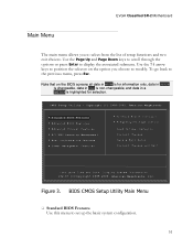
... Configure Frequency/Voltage Control Load Optimal Defaults Discard Changes Save & Exit Setup Discard Changes and Exit Configure Time and Date. Figure 3. BIOS CMOS Setup Utility Main Menu Standard BIOS Features Use this menu to the previous menu, press Esc. v02.67 (C)Copyright 1985-2009, American Megatrends, Inc. Display System Information... To go back to set up the basic system configuration. 51 CMOS Setup Utility - Use the Page Up and Page Down keys to scroll through the options...
... Configure Frequency/Voltage Control Load Optimal Defaults Discard Changes Save & Exit Setup Discard Changes and Exit Configure Time and Date. Figure 3. BIOS CMOS Setup Utility Main Menu Standard BIOS Features Use this menu to the previous menu, press Esc. v02.67 (C)Copyright 1985-2009, American Megatrends, Inc. Display System Information... To go back to set up the basic system configuration. 51 CMOS Setup Utility - Use the Page Up and Page Down keys to scroll through the options...

User Guide
Page 52
...as SATA and USB 3.0 configuration.. Advanced Chipset Features Use this menu to set up onboard peripherals such as USB, LAN, and MAC control. PCI/PNP Resource Management Use this menu to configure power management, power on, and sleep features. Boot Configuration Features Use this menu to modify the system's Plug-and-Play and PCI configurations. Power Management Features Use this menu to configure power management, power on the CMOS Setup Utility main menu are commands rather than submenus: Load Optimal Defaults Load default system settings. ...
...as SATA and USB 3.0 configuration.. Advanced Chipset Features Use this menu to set up onboard peripherals such as USB, LAN, and MAC control. PCI/PNP Resource Management Use this menu to configure power management, power on, and sleep features. Boot Configuration Features Use this menu to modify the system's Plug-and-Play and PCI configurations. Power Management Features Use this menu to configure power management, power on the CMOS Setup Utility main menu are commands rather than submenus: Load Optimal Defaults Load default system settings. ...
User Guide
Page 55
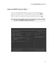
... [Disabled] E-SATA Controller (BackPanel) [Auto] Configure E-SATA as [AHCI Mode] E-SATA Boot [Enabled] SATA 3.0 Storage Controller [Enabled] Help Item Main Level Select Removable Boot Device Priority Move Enter:Select +/-/:Value F10:Save ESC:Exit F1:General Help F5:Previous Values F7:Optimized Defaults 55 EVGA Classified SR-2 Motherboard Advanced BIOS Features Menu Access the Advanced BIOS Features menu from the CMOS Setup Utility screen. Use the + and - To go back to modify. Press Enter to display the sub-menu. keys to scroll through the options or press Enter...
... [Disabled] E-SATA Controller (BackPanel) [Auto] Configure E-SATA as [AHCI Mode] E-SATA Boot [Enabled] SATA 3.0 Storage Controller [Enabled] Help Item Main Level Select Removable Boot Device Priority Move Enter:Select +/-/:Value F10:Save ESC:Exit F1:General Help F5:Previous Values F7:Optimized Defaults 55 EVGA Classified SR-2 Motherboard Advanced BIOS Features Menu Access the Advanced BIOS Features menu from the CMOS Setup Utility screen. Use the + and - To go back to modify. Press Enter to display the sub-menu. keys to scroll through the options or press Enter...

User Guide
Page 56
SATA Configuration Use this to configure your storage drivers and to use AHCI mode for Windows Vista / Windows 7, it is recommended to enable RAID or switch between IDE and AHCI mode. E-SATA Controller (Back panel) This option allows you to enable or disable the IO panel E-SATA ports. 56 AHCI Configuration This menu will allow you to change advanced AHCI settings, such as S.M.A.R.T. status and more. Please note for new system installations.
SATA Configuration Use this to configure your storage drivers and to use AHCI mode for Windows Vista / Windows 7, it is recommended to enable RAID or switch between IDE and AHCI mode. E-SATA Controller (Back panel) This option allows you to enable or disable the IO panel E-SATA ports. 56 AHCI Configuration This menu will allow you to change advanced AHCI settings, such as S.M.A.R.T. status and more. Please note for new system installations.

User Guide
Page 58
...to enable Legacy USB support, force USB 1.1 mode and more. It is not recommended to set advanced PCI-E options, such as Payload size. Advanced Chipset Features Advanced Chipset Settings USB Configuration [Press Enter] PCI Express Configuration [Press Enter] HD Audio [Enabled] USB 3.0 Controller [Enabled] Marvell LAN 1 [Enabled] Marvell LAN 2 [Enabled] LAN Boot [Disabled] P80 Show CPU0 Temperature [Enabled] Help Item Configure the USB support Move Enter:Select +/-/:Value F10:Save ESC:Exit F1:General Help F7:Previous Values F9:Optimized Defaults USB...
...to enable Legacy USB support, force USB 1.1 mode and more. It is not recommended to set advanced PCI-E options, such as Payload size. Advanced Chipset Features Advanced Chipset Settings USB Configuration [Press Enter] PCI Express Configuration [Press Enter] HD Audio [Enabled] USB 3.0 Controller [Enabled] Marvell LAN 1 [Enabled] Marvell LAN 2 [Enabled] LAN Boot [Disabled] P80 Show CPU0 Temperature [Enabled] Help Item Configure the USB support Move Enter:Select +/-/:Value F10:Save ESC:Exit F1:General Help F7:Previous Values F9:Optimized Defaults USB...

User Guide
Page 59
... using an external Network Controller, such as an EVGA Killer Xeno card. P80 Show CPU0 Temperature When this function is enabled the onboard Post Port LED will display the CPU0 (primary) temperature. 59 EVGA Classified SR-2 Motherboard HD Audio Use this function to leave this enabled, unless you are using an external Network Controller, such as an EVGA Killer Xeno card. Marvell LAN 2 This function allows you to enable or disable the onboard secondary network controller...
... using an external Network Controller, such as an EVGA Killer Xeno card. P80 Show CPU0 Temperature When this function is enabled the onboard Post Port LED will display the CPU0 (primary) temperature. 59 EVGA Classified SR-2 Motherboard HD Audio Use this function to leave this enabled, unless you are using an external Network Controller, such as an EVGA Killer Xeno card. Marvell LAN 2 This function allows you to enable or disable the onboard secondary network controller...
User Guide
Page 68
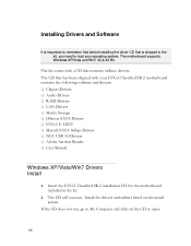
... Bit The kit comes with a CD that has been shipped with your operating system. Install the drivers and utilities listed on the CD to load your EVGA Classified SR-2 motherboard contains the following software and drivers: Chipset Drivers Audio Drivers RAID Drivers LAN Drivers Matrix Storage JMicron SATA Drivers EVGA E-LEET Marvell SATA 6Gbps Drivers NEC USB 3.0 Drivers Adobe Acrobat Reader User Manual Windows XP/Vista/Win7 Drivers Install 1. Installing Drivers and Software...
... Bit The kit comes with a CD that has been shipped with your operating system. Install the drivers and utilities listed on the CD to load your EVGA Classified SR-2 motherboard contains the following software and drivers: Chipset Drivers Audio Drivers RAID Drivers LAN Drivers Matrix Storage JMicron SATA Drivers EVGA E-LEET Marvell SATA 6Gbps Drivers NEC USB 3.0 Drivers Adobe Acrobat Reader User Manual Windows XP/Vista/Win7 Drivers Install 1. Installing Drivers and Software...


