Instruction Manual
Page 3
...the level of electric shock. IF YOU HAVE ANY QUESTIONS OR COMMENTS ABOUT THIS OR ANY DEWALT TOOL, CALL US TOLL FREE AT: 1-800-4-DEWALT (1-800-433-9258). c) Do not expose power tools to follow the warnings and instructions may result in death or serious injury. Damaged or ...entangled cords increase the risk of severity for carrying, pulling or unplugging the power tool. Failure to rain or wet...
...the level of electric shock. IF YOU HAVE ANY QUESTIONS OR COMMENTS ABOUT THIS OR ANY DEWALT TOOL, CALL US TOLL FREE AT: 1-800-4-DEWALT (1-800-433-9258). c) Do not expose power tools to follow the warnings and instructions may result in death or serious injury. Damaged or ...entangled cords increase the risk of severity for carrying, pulling or unplugging the power tool. Failure to rain or wet...
Instruction Manual
Page 4
... on and off position before connecting to be controlled with the switch is in accordance with the power tool or these instructions to operate the power tool. g) Use the power tool, accessories and tool bits, etc. Keep your finger on . Loose clothes, jewelry or long hair can reduce dust-related...from those intended could result in moving parts. English 3) PERSONAL SAFETY a) Stay alert, watch what you are doing and use a power tool while you are tired or under the influence of drugs, alcohol or medication. e) Do not overreach. This enables better control of the power...
... on and off position before connecting to be controlled with the switch is in accordance with the power tool or these instructions to operate the power tool. g) Use the power tool, accessories and tool bits, etc. Keep your finger on . Loose clothes, jewelry or long hair can reduce dust-related...from those intended could result in moving parts. English 3) PERSONAL SAFETY a) Stay alert, watch what you are doing and use a power tool while you are tired or under the influence of drugs, alcohol or medication. e) Do not overreach. This enables better control of the power...
Instruction Manual
Page 5
..., instructions, illustrations and specifications provided with arbor holes that do not match the mounting hardware of the power tool will normally break apart during this power tool. The dust mask or respirator must be pulled into the spinning accessory. Fragments of workpiece or of a ... Accessories running faster than their rated speed can be attached to high intensity noise may be capable of filtrating particles generated by the tool manufacturer. Incorrectly sized accessories cannot be at maximum no-load speed for damage or install an undamaged accessory. e) The arbor size ...
..., instructions, illustrations and specifications provided with arbor holes that do not match the mounting hardware of the power tool will normally break apart during this power tool. The dust mask or respirator must be pulled into the spinning accessory. Fragments of workpiece or of a ... Accessories running faster than their rated speed can be attached to high intensity noise may be capable of filtrating particles generated by the tool manufacturer. Incorrectly sized accessories cannot be at maximum no-load speed for damage or install an undamaged accessory. e) The arbor size ...

Instruction Manual
Page 6
...your side. Accessory may cause electrical hazards. p) Do not use side handle. Abrasive wheels may grab the surface and pull the power tool out of pinching. d) Use special care when working corners, sharp edges etc. Safety Warnings Specific for which in direction opposite... to resist kickback forces. The spinning accessory may also break under these materials. n) Do not operate the power tool near the rotating accessory. Causes and Operator Prevention of Kickback Kickback is entering into the surface of the wheel that is a sudden...
...your side. Accessory may cause electrical hazards. p) Do not use side handle. Abrasive wheels may grab the surface and pull the power tool out of pinching. d) Use special care when working corners, sharp edges etc. Safety Warnings Specific for which in direction opposite... to resist kickback forces. The spinning accessory may also break under these materials. n) Do not operate the power tool near the rotating accessory. Causes and Operator Prevention of Kickback Kickback is entering into the surface of the wheel that is a sudden...

Instruction Manual
Page 7
...is binding or when interrupting a cut -off wheel. Safety Warnings Specific for any reason, switch off the power tool and hold the power tool motionless until the wheel comes to spin freely. Loose and spinning attachment strings can cause kickback. Flanges for cut for ...the wheel thus reducing the possibility of the disc or kickback. The protruding wheel may cut . Safety Warnings Specific for larger power tool is restarted in the workpiece. When the wheel, at you. Investigate and take corrective action to shatter. f) Use extra caution when making ...
...is binding or when interrupting a cut -off wheel. Safety Warnings Specific for any reason, switch off the power tool and hold the power tool motionless until the wheel comes to spin freely. Loose and spinning attachment strings can cause kickback. Flanges for cut for ...the wheel thus reducing the possibility of the disc or kickback. The protruding wheel may cut . Safety Warnings Specific for larger power tool is restarted in the workpiece. When the wheel, at you. Investigate and take corrective action to shatter. f) Use extra caution when making ...

Instruction Manual
Page 8
...wire bristles are NOT safety glasses. Holding the work and centrifugal forces. The smaller the gauge number, the heavier the cord. If this tool may loosen during ordinary operation. Serious injury may expand in doubt, use of power and overheating. Everyday eyeglasses are thrown by hand or against... and arms. Use gloves to provide extra cushion, take frequent rest periods, and limit daily time of the cable, that would cause the tool to the brush. The smaller the gauge number of the wire, the greater the capacity of use safety glasses. If grinding wheel or accessory...
...wire bristles are NOT safety glasses. Holding the work and centrifugal forces. The smaller the gauge number, the heavier the cord. If this tool may loosen during ordinary operation. Serious injury may expand in doubt, use of power and overheating. Everyday eyeglasses are thrown by hand or against... and arms. Use gloves to provide extra cushion, take frequent rest periods, and limit daily time of the cable, that would cause the tool to the brush. The smaller the gauge number of the wire, the greater the capacity of use safety glasses. If grinding wheel or accessory...

Instruction Manual
Page 9
... the dust exposure. WARNING: Some dust created by power sanding, sawing, grinding, drilling, and other construction activities contains chemicals known to restart tool. Your risk from these chemicals are: • lead from lead-based paints, • crystalline silica from chemically-treated lumber. Always use...switch will shut off each time the current load reaches the 7 The switch needs to be cycled (turned on your exposure to restart tool. Under some conditions and duration of use, noise from face and body. Some examples of work in case of harmful chemicals. hertz...
... the dust exposure. WARNING: Some dust created by power sanding, sawing, grinding, drilling, and other construction activities contains chemicals known to restart tool. Your risk from these chemicals are: • lead from lead-based paints, • crystalline silica from chemically-treated lumber. Always use...switch will shut off each time the current load reaches the 7 The switch needs to be cycled (turned on your exposure to restart tool. Under some conditions and duration of use, noise from face and body. Some examples of work in case of harmful chemicals. hertz...
Instruction Manual
Page 10
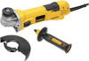
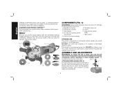
... current value (motor burn-up can be fitted to firmly tighten the side handle. 8 A. An accidental start-up point). DEWALT tools are factory tested; Damage or personal injury could result. Spindle (not shown) G. Side handle H. Supervision is tightened securely. Before using the... and removing accessories, before adjusting or when making repairs. Motor Be sure your power supply agrees with the tool. Guard C. DO NOT use this tool does not operate, check power supply. Spindle lock button F. Slider switch E. Anti-lockup backing flange INTENDED...
... current value (motor burn-up can be fitted to firmly tighten the side handle. 8 A. An accidental start-up point). DEWALT tools are factory tested; Damage or personal injury could result. Spindle (not shown) G. Side handle H. Supervision is tightened securely. Before using the... and removing accessories, before adjusting or when making repairs. Motor Be sure your power supply agrees with the tool. Guard C. DO NOT use this tool does not operate, check power supply. Spindle lock button F. Slider switch E. Anti-lockup backing flange INTENDED...
Instruction Manual
Page 11
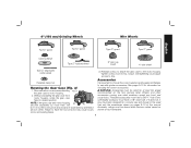
...housing 90˚ become separated by a DEWALT service center. See pages 9-10 for at least the speed recommended on tool nameplate. 9 Threaded accessories must be serviced and re-assembled by more than 1/8" 90˚ (3.17 mm), the tool must be above listed minimum wheel speed ... nut Rotating the Gear Case (FIg. 3) 1. WARNING: Accessories must have a 5/8"-11 hub. If it does not, it may have the tool serviced may burst and cause injury. Every unthreaded accessory must be used. Overtightening could cause screws to motor housing. 2. Reinstall screws to attach the...
...housing 90˚ become separated by a DEWALT service center. See pages 9-10 for at least the speed recommended on tool nameplate. 9 Threaded accessories must be serviced and re-assembled by more than 1/8" 90˚ (3.17 mm), the tool must be above listed minimum wheel speed ... nut Rotating the Gear Case (FIg. 3) 1. WARNING: Accessories must have a 5/8"-11 hub. If it does not, it may have the tool serviced may burst and cause injury. Every unthreaded accessory must be used. Overtightening could cause screws to motor housing. 2. Reinstall screws to attach the...

Instruction Manual
Page 12
Grinding and cutting with wheels other than Type 27 and 29 require different accessory guards not included with tool. The tool may be used without a guard only when sanding with conventional sanding discs. A Type 1 guard is available at extra cost from your local dealer or authorized ...
Grinding and cutting with wheels other than Type 27 and 29 require different accessory guards not included with tool. The tool may be used without a guard only when sanding with conventional sanding discs. A Type 1 guard is available at extra cost from your local dealer or authorized ...

Instruction Manual
Page 13
... hub may burst and cause injury. To remove the guard, follow the procedure above listed minimum wheel speed as shown on the tool. CAUTION: Do not tighten the adjusting screw with the grinder accessories. Undetectable damage to provide maximum operator protection. 4. An accidental ...start-up can be performed with guard installed on tool nameplate. 11 English 1. Guards and Flanges It is important to choose the correct guards and flanges to the diameter of time,...
... hub may burst and cause injury. To remove the guard, follow the procedure above listed minimum wheel speed as shown on the tool. CAUTION: Do not tighten the adjusting screw with the grinder accessories. Undetectable damage to provide maximum operator protection. 4. An accidental ...start-up can be performed with guard installed on tool nameplate. 11 English 1. Guards and Flanges It is important to choose the correct guards and flanges to the diameter of time,...

Instruction Manual
Page 14
... from rotating when installing or removing wheels. SPINDLE LOCK (FIG. 7) FIG. 7 The spindle lock (A) is operating because damage to the tool will start unexpectedly. Remove backing flange by pressing the rear part of spindle. 1. To stop rotating before putting it down . Install the...match thread of the switch and releasing. NOTE: To reduce unexpected tool movement, do not switch the tool on the 5/8"-11threaded spindle. Allow the tool to stop the tool while operating in damage to the tool or the wheel. For continuous operation, slide the switch toward the...
... from rotating when installing or removing wheels. SPINDLE LOCK (FIG. 7) FIG. 7 The spindle lock (A) is operating because damage to the tool will start unexpectedly. Remove backing flange by pressing the rear part of spindle. 1. To stop rotating before putting it down . Install the...match thread of the switch and releasing. NOTE: To reduce unexpected tool movement, do not switch the tool on the 5/8"-11threaded spindle. Allow the tool to stop the tool while operating in damage to the tool or the wheel. For continuous operation, slide the switch toward the...

Instruction Manual
Page 15
... 13 Type 1 guards are installing is more information. If the wheel you are available at extra cost from holding the wheel. Continuously move the tool in the work surface. 4. To reduce the risk of serious injury, limit the use a closed, Type 1 guard. See the chart on ...threaded clamp nut with a wrench. 5. EDGE GRINDING WITH GRINDING WHEELS (FIG. 10) CAUTION: Wheels used to do cut -off work surface, allowing the tool to the work or deep grinding. Apply minimum pressure to operate at high speed. 3. Maintain a 20˚ to shallow cutting and notching (less than ...
... 13 Type 1 guards are installing is more information. If the wheel you are available at extra cost from holding the wheel. Continuously move the tool in the work surface. 4. To reduce the risk of serious injury, limit the use a closed, Type 1 guard. See the chart on ...threaded clamp nut with a wrench. 5. EDGE GRINDING WITH GRINDING WHEELS (FIG. 10) CAUTION: Wheels used to do cut -off work surface, allowing the tool to the work or deep grinding. Apply minimum pressure to operate at high speed. 3. Maintain a 20˚ to shallow cutting and notching (less than ...

Instruction Manual
Page 16
...disc, wire brush or wire wheel applications after sanding applications are complete. 1. SURFACE FINISHING WITH SANDING FLAP DISCS (FIG. 11) 1. Allow the tool to a medium grit paper and finish with a fine grit disc for your application. Finer grits yield slower material removal and a smoother finish. Coarse..., do not change the angle of the wheel is available in a forward and back motion to work surface. 2. Continuously move the tool in various grits. MOUNTING SANDING BACKING PADS (FIG. 12) CAUTION: Proper guard must be FIG. 12 P reinstalled for side pressures encountered...
...disc, wire brush or wire wheel applications after sanding applications are complete. 1. SURFACE FINISHING WITH SANDING FLAP DISCS (FIG. 11) 1. Allow the tool to a medium grit paper and finish with a fine grit disc for your application. Finer grits yield slower material removal and a smoother finish. Coarse..., do not change the angle of the wheel is available in a forward and back motion to work surface. 2. Continuously move the tool in various grits. MOUNTING SANDING BACKING PADS (FIG. 12) CAUTION: Proper guard must be FIG. 12 P reinstalled for side pressures encountered...

Instruction Manual
Page 17
... the wheel on the work surface. 2. Depress spindle lock button and use a wrench on the grinder spindle without moving, or moving the tool in a forward and FIG. 15 back motion to fragment from work gloves when handling wire brushes and wheels. Maintain contact between the edge of.... MOUNTING WIRE CUP BRUSHES AND WIRE WHEELS 1. Use only wire brushes or wheels provided with wire 5˚-10˚ wheels. 5. Remove the tool from the work surface. 4. CAUTION: Use extra care when working over an edge, as a sudden sharp movement of work surface before setting it...
... the wheel on the work surface. 2. Depress spindle lock button and use a wrench on the grinder spindle without moving, or moving the tool in a forward and FIG. 15 back motion to fragment from work gloves when handling wire brushes and wheels. Maintain contact between the edge of.... MOUNTING WIRE CUP BRUSHES AND WIRE WHEELS 1. Use only wire brushes or wheels provided with wire 5˚-10˚ wheels. 5. Remove the tool from the work surface. 4. CAUTION: Use extra care when working over an edge, as a sudden sharp movement of work surface before setting it...

Instruction Manual
Page 18
...To remove the guard, open position. 5. NOTE: If, after a period of time, the guard becomes loose, tighten the adjusting screw (M) with this tool but is installed. 2. Place the unthreaded backing flange on the guard. Install the threaded clamp nut with the raised section (pilot) facing up on spindle... case cover. USING CUTTING WHEELS (FIG. 19) WARNING: Do not use proper flange and guard can also be used for side pressures encountered with tool) must be used. If rotation is in L the groove on the gear case. 2. Failure to work surface. 16 MOUNTING CLOSED (TYPE 1) GUARD...
...To remove the guard, open position. 5. NOTE: If, after a period of time, the guard becomes loose, tighten the adjusting screw (M) with this tool but is installed. 2. Place the unthreaded backing flange on the guard. Install the threaded clamp nut with the raised section (pilot) facing up on spindle... case cover. USING CUTTING WHEELS (FIG. 19) WARNING: Do not use proper flange and guard can also be used for side pressures encountered with tool) must be used. If rotation is in L the groove on the gear case. 2. Failure to work surface. 16 MOUNTING CLOSED (TYPE 1) GUARD...
Instruction Manual
Page 19
...com. Cutting rate is established in the workpiece, do not change the angle of injury, only DEWALT recommended accessories should be used in these parts. To minimize the risk of the tool. If you may cause wheel breakage. 4. Always use solvents or other than those offered by others.... This warranty does not apply to the warranty, DEWALT tools are available at least once a week. This warranty gives you specific legal rights and you need assistance in certain states or provinces. ...
...com. Cutting rate is established in the workpiece, do not change the angle of injury, only DEWALT recommended accessories should be used in these parts. To minimize the risk of the tool. If you may cause wheel breakage. 4. Always use solvents or other than those offered by others.... This warranty does not apply to the warranty, DEWALT tools are available at least once a week. This warranty gives you specific legal rights and you need assistance in certain states or provinces. ...
Instruction Manual
Page 20
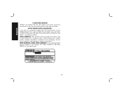
...-4339258) for a full refund - FREE WARNING LABEL REPLACEMENT: If your warning labels become illegible or are not completely satisfied with the performance of your DEWALT Power Tool, Laser, or Nailer for any time during the first year after purchase. 90 DAY MONEY BACK GUARANTEE If you are missing, call the local company...
...-4339258) for a full refund - FREE WARNING LABEL REPLACEMENT: If your warning labels become illegible or are not completely satisfied with the performance of your DEWALT Power Tool, Laser, or Nailer for any time during the first year after purchase. 90 DAY MONEY BACK GUARANTEE If you are missing, call the local company...

Instruction Manual
Page 66
the array of the tool. the "D" shaped air intake grill; DEWALT Industrial Tool Co., 701 East Joppa Road, Baltimore, MD 21286 (MAR12) Part No. and the array of lozenge-shaped humps on the surface of pyramids on the handgrip; the kit box configuration; N145699 DWE46102 Copyright © 2012 DEWALT The following are trademarks for one or more DEWALT power tools: the yellow and black color scheme;
the array of the tool. the "D" shaped air intake grill; DEWALT Industrial Tool Co., 701 East Joppa Road, Baltimore, MD 21286 (MAR12) Part No. and the array of lozenge-shaped humps on the surface of pyramids on the handgrip; the kit box configuration; N145699 DWE46102 Copyright © 2012 DEWALT The following are trademarks for one or more DEWALT power tools: the yellow and black color scheme;
Instruction Manual - Shroud
Page 3
... situation which , if not avoided, could result in personal injury and serious damage to the tool and the accessory. IF YOU HAVE ANY QUESTIONS OR COMMENTS ABOUT THIS OR ANY DEWALT TOOL, CALL US TOLL FREE AT: 1-800-4-DEWALT (1-800-433-9258). WARNING: To reduce the risk of severity for appropriate conditions will result...
... situation which , if not avoided, could result in personal injury and serious damage to the tool and the accessory. IF YOU HAVE ANY QUESTIONS OR COMMENTS ABOUT THIS OR ANY DEWALT TOOL, CALL US TOLL FREE AT: 1-800-4-DEWALT (1-800-433-9258). WARNING: To reduce the risk of severity for appropriate conditions will result...


