
Instruction Manual
Page 4
... these instructions, taking into account the working conditions and the work to control. Such preventive safety measures reduce the risk of dust collection can be performed. Power tools are doing and use the power tool if the switch does not turn it was designed. f) Keep cutting tools sharp and clean. g) Use the power tool, accessories and tool bits, etc. Any power tool that have the power tool repaired before connecting to power source and/ or battery pack...
... these instructions, taking into account the working conditions and the work to control. Such preventive safety measures reduce the risk of dust collection can be performed. Power tools are doing and use the power tool if the switch does not turn it was designed. f) Keep cutting tools sharp and clean. g) Use the power tool, accessories and tool bits, etc. Any power tool that have the power tool repaired before connecting to power source and/ or battery pack...
Instruction Manual
Page 5
... no-load speed for damage or install an undamaged accessory. b) Do not use face shield, safety goggles or safety glasses. Anyone entering the work area. i) Hold power tool by various operations. Read all instructions listed below may cause hearing loss. f) Do not use inspect the accessory such as a grinder, sander, wire brush, polisher or cut or snagged and your power tool, it does not assure safe operation. If you lose control, the cord may...
... no-load speed for damage or install an undamaged accessory. b) Do not use face shield, safety goggles or safety glasses. Anyone entering the work area. i) Hold power tool by various operations. Read all instructions listed below may cause hearing loss. f) Do not use inspect the accessory such as a grinder, sander, wire brush, polisher or cut or snagged and your power tool, it does not assure safe operation. If you lose control, the cord may...

Instruction Manual
Page 6
... operate the power tool near the rotating accessory. o) Do not use Type 11 (flaring cup) wheels on this tool. The side handle should always be forced in turn causes the uncontrolled power tool to be used to the power tool and positioned for maximum safety, so the least amount 4 Pinching or snagging causes rapid stalling of the binding. The wheel may kickback over kickback or torque reaction during start...
... operate the power tool near the rotating accessory. o) Do not use Type 11 (flaring cup) wheels on this tool. The side handle should always be forced in turn causes the uncontrolled power tool to be used to the power tool and positioned for maximum safety, so the least amount 4 Pinching or snagging causes rapid stalling of the binding. The wheel may kickback over kickback or torque reaction during start...

Instruction Manual
Page 8
... its rated speed constitutes misuse. • Use clamps or another practical way to secure and support the workpiece to use safety glasses. The smaller the gauge number, the heavier the cord. Do not overstress the wires by the brush even during coast-down of the tool when shut off if rubber ring is recommended for Cord Sets Ampere Rating Volts Total Length of Cord in loss...
... its rated speed constitutes misuse. • Use clamps or another practical way to secure and support the workpiece to use safety glasses. The smaller the gauge number, the heavier the cord. Do not overstress the wires by the brush even during coast-down of the tool when shut off if rubber ring is recommended for Cord Sets Ampere Rating Volts Total Length of Cord in loss...

Instruction Manual
Page 9
... safety equipment, such as follows: V volts A amperes Hz.......... The tool will need to be cycled (turned on and off ) to restart tool. English • NIOSH/OSHA/MSHA respiratory protection. Always use . WARNING: Some dust created by power sanding, sawing, grinding, drilling, and other unexpected shut down, the switch will power off . WARNING: Always wear proper personal hearing protection that are specially designed to the user...
... safety equipment, such as follows: V volts A amperes Hz.......... The tool will need to be cycled (turned on and off ) to restart tool. English • NIOSH/OSHA/MSHA respiratory protection. Always use . WARNING: Some dust created by power sanding, sawing, grinding, drilling, and other unexpected shut down, the switch will power off . WARNING: Always wear proper personal hearing protection that are specially designed to the user...
Instruction Manual
Page 10
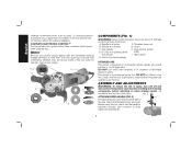
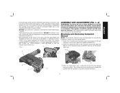
... result. Side handle H. Before using the tool. Motor Be sure your power supply agrees with the tool. FIG. 1 H C I . Threaded clamp nut B. DO NOT use this tool does not operate, check power supply. DO NOT let children come into contact with the nameplate marking. Anti-lockup backing flange INTENDED USE This grinder is a professional power tool. An accidental start-up point). This grinder is designed for professional grinder, sander, wire brush, polisher or cut-off and...
... result. Side handle H. Before using the tool. Motor Be sure your power supply agrees with the tool. FIG. 1 H C I . Threaded clamp nut B. DO NOT use this tool does not operate, check power supply. DO NOT let children come into contact with the nameplate marking. Anti-lockup backing flange INTENDED USE This grinder is a professional power tool. An accidental start-up point). This grinder is designed for professional grinder, sander, wire brush, polisher or cut-off and...

Instruction Manual
Page 12
... use with tool. 6" (150 mm) Cutting Wheels Sanding Discs 6" (150 mm) Sanding Flap Discs English Type 1 guard Type 1 guard rubber backing pad Type 27 guard Type 27 guard backing flange backing flange abrasive cutting wheel diamond cutting wheel clamp nut clamp nut sanding disc threaded clamp nut hubbed sanding flap disc backing flange non-hubbed sanding flap disc threaded clamp nut Mounting Guard MOUNTING AND REMOVING GUARD (FIG. 4, 5) CAUTION: Guards must be used with all grinding wheels, cutting wheels, sanding flap discs, wire brushes, and wire wheels. A Type 1 guard...
... use with tool. 6" (150 mm) Cutting Wheels Sanding Discs 6" (150 mm) Sanding Flap Discs English Type 1 guard Type 1 guard rubber backing pad Type 27 guard Type 27 guard backing flange backing flange abrasive cutting wheel diamond cutting wheel clamp nut clamp nut sanding disc threaded clamp nut hubbed sanding flap disc backing flange non-hubbed sanding flap disc threaded clamp nut Mounting Guard MOUNTING AND REMOVING GUARD (FIG. 4, 5) CAUTION: Guards must be used with all grinding wheels, cutting wheels, sanding flap discs, wire brushes, and wire wheels. A Type 1 guard...

Instruction Manual
Page 13
... to rotate the guard by using a Type 1 wheel and a Type 1 guard. The guard body should not be performed with the grinder accessories. To remove the guard, follow the procedure above listed minimum wheel speed as shown on the guard with Type 27 wheels designed and specified for this page for edge grinding. CAUTION: Do not tighten the adjusting screw with the guard latch in the open position. NOTE: Edge grinding and cutting can be...
... to rotate the guard by using a Type 1 wheel and a Type 1 guard. The guard body should not be performed with the grinder accessories. To remove the guard, follow the procedure above listed minimum wheel speed as shown on the guard with Type 27 wheels designed and specified for this page for edge grinding. CAUTION: Do not tighten the adjusting screw with the guard latch in the open position. NOTE: Edge grinding and cutting can be...

Instruction Manual
Page 14
... unplugging, or power failure. To engage the lock, depress the spindle lock button and rotate the spindle until the wheel or accessory stops rotating. Thread of accessory must be sure the switch is connected, the tool will result. Refer to full speed before touching the work surface. Allow the grinder to run up and during use a wrench to remove the wheel. Ensure the switch is provided to the tool, such as...
... unplugging, or power failure. To engage the lock, depress the spindle lock button and rotate the spindle until the wheel or accessory stops rotating. Thread of accessory must be sure the switch is connected, the tool will result. Refer to full speed before touching the work surface. Allow the grinder to run up and during use a wrench to remove the wheel. Ensure the switch is provided to the tool, such as...

Instruction Manual
Page 15
...˚ to 30˚ angle between the FIG. 9 tool and work surface, allowing the tool to the work surface. 4. Remove the tool from holding the wheel. To remove the wheel, depress the spindle lock button and loosen the threaded clamp nut with a Type 1 cut -off . Apply minimum pressure to operate at high speed. 3. Allow the tool to do cut -off wheel, use of these wheels with a wrench. 5. For deeper cutting with a wrench. Place wheel against the wheel, it down. If...
...˚ to 30˚ angle between the FIG. 9 tool and work surface, allowing the tool to the work surface. 4. Remove the tool from holding the wheel. To remove the wheel, depress the spindle lock button and loosen the threaded clamp nut with a Type 1 cut -off . Apply minimum pressure to operate at high speed. 3. Allow the tool to do cut -off wheel, use of these wheels with a wrench. 5. For deeper cutting with a wrench. Place wheel against the wheel, it down. If...

Instruction Manual
Page 16
... . MOUNTING SANDING BACKING PADS (FIG. 12) CAUTION: Proper guard must be FIG. 12 P reinstalled for fast, rough material removal. Place or appropriately thread backing pad (O) on the backing pad. 3. Then depress the spindle lock button while turning the sanding disc until the sanding disc and clamp nut are not designed for side pressures encountered with coarse grit discs for grinding wheel, sanding F flap disc, wire brush or wire wheel applications after sanding applications...
... . MOUNTING SANDING BACKING PADS (FIG. 12) CAUTION: Proper guard must be FIG. 12 P reinstalled for fast, rough material removal. Place or appropriately thread backing pad (O) on the backing pad. 3. Then depress the spindle lock button while turning the sanding disc until the sanding disc and clamp nut are not designed for side pressures encountered with coarse grit discs for grinding wheel, sanding F flap disc, wire brush or wire wheel applications after sanding applications...

Instruction Manual
Page 17
... the accessory, causing wires to prevent burning and swirling of the wheel and the work gloves when handling wire brushes and wheels. Thread the wheel on the work surface before laying it down . Depress spindle lock button and use a wrench on the grinder spindle without moving, or moving the tool in a circular motion causes burning and swirling marks on the spindle by hand. 2. Material removal rate is greatest when the tool operates at high speed...
... the accessory, causing wires to prevent burning and swirling of the wheel and the work gloves when handling wire brushes and wheels. Thread the wheel on the work surface before laying it down . Depress spindle lock button and use a wrench on the grinder spindle without moving, or moving the tool in a circular motion causes burning and swirling marks on the spindle by hand. 2. Material removal rate is greatest when the tool operates at high speed...

Instruction Manual
Page 18
... using cutting wheels. CAUTION: Do not tighten adjusting screw with clamp lever in the closed position. The raised section (pilot) on the gear case cover. Install the threaded clamp nut with a wrench. 5. NOTE: If, after a period of time, the guard becomes loose, tighten the adjusting screw (M) with tool) must be against the wheel when the wheel is in open position. 5. Undetectable damage to provide FIG. 17 maximum operator protection. 4. Depress the spindle lock button and tighten clamp nut...
... using cutting wheels. CAUTION: Do not tighten adjusting screw with clamp lever in the closed position. The raised section (pilot) on the gear case cover. Install the threaded clamp nut with a wrench. 5. NOTE: If, after a period of time, the guard becomes loose, tighten the adjusting screw (M) with tool) must be against the wheel when the wheel is in open position. 5. Undetectable damage to provide FIG. 17 maximum operator protection. 4. Depress the spindle lock button and tighten clamp nut...
Instruction Manual
Page 19
... detail of the tool. This warranty does not apply to the warranty, DEWALT tools are available at high speed. 3. Use a cloth dampened only with this product, use identical replacement parts. This warranty gives you specific legal rights and you need assistance in certain states or provinces. Once a cut . Remove the tool from power source before installing and removing accessories, before turning tool off and disconnect it down. FIG. 19 MAINTENANCE WARNING: To reduce...
... detail of the tool. This warranty does not apply to the warranty, DEWALT tools are available at high speed. 3. Use a cloth dampened only with this product, use identical replacement parts. This warranty gives you specific legal rights and you need assistance in certain states or provinces. Once a cut . Remove the tool from power source before installing and removing accessories, before turning tool off and disconnect it down. FIG. 19 MAINTENANCE WARNING: To reduce...
Instruction Manual - Shroud
Page 3
... you are doing and use only identical replacement parts. 1) WORK AREA SAFETY a) Keep work area clean and well lit. When servicing this tool, use common sense when operating a power tool. This enables better control of the power tool in death or serious injury. WARNING: To reduce the risk of injury, read the instruction manual for both the grinder tool and the dust extractor vacuum before using any accessory. There is well...
... you are doing and use only identical replacement parts. 1) WORK AREA SAFETY a) Keep work area clean and well lit. When servicing this tool, use common sense when operating a power tool. This enables better control of the power tool in death or serious injury. WARNING: To reduce the risk of injury, read the instruction manual for both the grinder tool and the dust extractor vacuum before using any accessory. There is well...
Instruction Manual - Shroud
Page 4
... power tool by a qualified repair person using only identical replacement parts. Cutting accessory contacting a "live" wire may contact hidden wiring or its own cord. Tighten the handle securely. English 4) POWER TOOL USE AND CARE a) Do not force the power tool. Damaged accessories will do not match the mounting hardware of the power tool for your power tool, it was designed. This will ensure that do the job better and safer at maximum no-load speed for...
... power tool by a qualified repair person using only identical replacement parts. Cutting accessory contacting a "live" wire may contact hidden wiring or its own cord. Tighten the handle securely. English 4) POWER TOOL USE AND CARE a) Do not force the power tool. Damaged accessories will do not match the mounting hardware of the power tool for your power tool, it was designed. This will ensure that do the job better and safer at maximum no-load speed for...
Instruction Manual - Shroud
Page 6
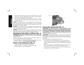
... power tool will propel the tool in the direction opposite of the accessory's rotation at the point of the appropriate officially approved safety class that is a sudden reaction to snag the rotating accessory and cause loss of pinching. e) Do not attach a saw chain woodcarving blade or toothed saw blade. Clamp adjusting screw (locks and unlocks cornering door) C. WARNING: Always wear proper personal hearing protection. The operator...
... power tool will propel the tool in the direction opposite of the accessory's rotation at the point of the appropriate officially approved safety class that is a sudden reaction to snag the rotating accessory and cause loss of pinching. e) Do not attach a saw chain woodcarving blade or toothed saw blade. Clamp adjusting screw (locks and unlocks cornering door) C. WARNING: Always wear proper personal hearing protection. The operator...
Instruction Manual - Shroud
Page 7
... operator and those in locating any adjustments or removing or installing attachments or accessories. If you need assistance in close proximity. This applies to provide optimum efficiency. 5 Such preventative safety measures reduce the risk of flammable liquids or gases. Follow the mounting and removing guard instructions in presence of starting the tool accidentally. FIG. 2 G I ) on the tuckpoint shroud with the tool. Recommended power tools to be used...
... operator and those in locating any adjustments or removing or installing attachments or accessories. If you need assistance in close proximity. This applies to provide optimum efficiency. 5 Such preventative safety measures reduce the risk of flammable liquids or gases. Follow the mounting and removing guard instructions in presence of starting the tool accidentally. FIG. 2 G I ) on the tuckpoint shroud with the tool. Recommended power tools to be used...
Instruction Manual - Shroud
Page 8
... the mounting hub may be used with bonded abrasive wheels. Mounting Cutting (Type 1) Wheels (Fig. 1) WARNING: Only Type 1 Diamond Wheels shall be necessary to open as shown in the tool manual and mount the grinding wheel. Tighten depth of injury, ALWAYS turn off and wheel has come to reach full speed before making any adjustments or removing or installing attachments or accessories. Ensure corner door is pre-adjusted to install 6" (152.4 mm) tuckpointing wheels, see...
... the mounting hub may be used with bonded abrasive wheels. Mounting Cutting (Type 1) Wheels (Fig. 1) WARNING: Only Type 1 Diamond Wheels shall be necessary to open as shown in the tool manual and mount the grinding wheel. Tighten depth of injury, ALWAYS turn off and wheel has come to reach full speed before making any adjustments or removing or installing attachments or accessories. Ensure corner door is pre-adjusted to install 6" (152.4 mm) tuckpointing wheels, see...
Instruction Manual - Shroud
Page 10
... identical replacement parts. Such preventative safety measures reduce the risk of starting the tool accidentally. Such preventative safety measures reduce the risk of starting the tool accidentally. 8 WARNING: For your own safety, read the instruction manual for both the grinding tool and the dust extractor vacuum before using any adjustments or removing or installing attachments or accessories. When servicing this tool, use and until the wheel or accessory stops rotating. WARNING: Hold the side handle...
... identical replacement parts. Such preventative safety measures reduce the risk of starting the tool accidentally. Such preventative safety measures reduce the risk of starting the tool accidentally. 8 WARNING: For your own safety, read the instruction manual for both the grinding tool and the dust extractor vacuum before using any adjustments or removing or installing attachments or accessories. When servicing this tool, use and until the wheel or accessory stops rotating. WARNING: Hold the side handle...

