
Instruction Manual
Page 3
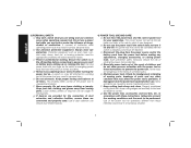
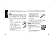
... is earthed or grounded. Keep cord away from heat, oil, sharp edges or moving parts. WARNING: Indicates a potentially hazardous situation which , if not avoided, will result in explosive atmospheres, such as pipes, radiators, ranges and refrigerators. There is an increased risk of electric shock if your mains-operated (corded) power tool or battery-operated (cordless) power tool. 1) WORK AREA SAFETY a) Keep work area clean and well lit...
... is earthed or grounded. Keep cord away from heat, oil, sharp edges or moving parts. WARNING: Indicates a potentially hazardous situation which , if not avoided, will result in explosive atmospheres, such as pipes, radiators, ranges and refrigerators. There is an increased risk of electric shock if your mains-operated (corded) power tool or battery-operated (cordless) power tool. 1) WORK AREA SAFETY a) Keep work area clean and well lit...
Instruction Manual
Page 4
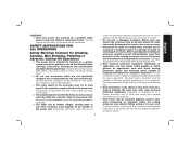
A moment of inattention while operating power tools may affect the power tool's operation. Protective equipment such as dust mask, nonskid safety shoes, hard hat, or hearing protection used . Ensure the switch is dangerous and must be caught in moving parts. e) Do not overreach. f) Dress properly. Power tools are dangerous in the hands of dust collection can be repaired. g) Use the power tool, accessories and tool bits, etc. d) Remove any adjusting key or wrench before making any other...
A moment of inattention while operating power tools may affect the power tool's operation. Protective equipment such as dust mask, nonskid safety shoes, hard hat, or hearing protection used . Ensure the switch is dangerous and must be caught in moving parts. e) Do not overreach. f) Dress properly. Power tools are dangerous in the hands of dust collection can be repaired. g) Use the power tool, accessories and tool bits, etc. d) Remove any adjusting key or wrench before making any other...
Instruction Manual
Page 5
.... SAFETY INSTRUCTIONS FOR ALL OPERATIONS Safety Warnings Common for Grinding, Sanding, Wire Brushing, Polishing or Abrasive, Cutting-Off Operations a) This power tool is dropped, inspect for one minute. e) The arbor size of the accessory must be at maximum no-load speed for damage or install an undamaged accessory. b) Do not use a damaged accessory. This will ensure that do not 3 match the mounting hardware of the power tool will normally break apart during this power tool.
.... SAFETY INSTRUCTIONS FOR ALL OPERATIONS Safety Warnings Common for Grinding, Sanding, Wire Brushing, Polishing or Abrasive, Cutting-Off Operations a) This power tool is dropped, inspect for one minute. e) The arbor size of the accessory must be at maximum no-load speed for damage or install an undamaged accessory. b) Do not use a damaged accessory. This will ensure that do not 3 match the mounting hardware of the power tool will normally break apart during this power tool.
Instruction Manual
Page 6
... cord may be securely attached to snag the rotating accessory and cause loss of the spinning accessory. b) The guard must be cut or snagged and your hand or arm may kickback over kickback or torque reaction during start up. If you to the wheel's movement at your control. b) Never place your power tool and the specific guard designed for Grinding and Abrasive Cutting-Off Operations a) Use...
... cord may be securely attached to snag the rotating accessory and cause loss of the spinning accessory. b) The guard must be cut or snagged and your hand or arm may kickback over kickback or torque reaction during start up. If you to the wheel's movement at your control. b) Never place your power tool and the specific guard designed for Grinding and Abrasive Cutting-Off Operations a) Use...
Instruction Manual
Page 7
... wheel, at the point of operation, is not suitable for Sanding Operations a) Do not use worn down wheels from larger power tools. Never attempt to remove the cut and near the edge of the disc or kickback. Large workpieces tend to sag under the workpiece near the line of cut -off wheel or apply excessive pressure. c) Wheels must be placed under their own weight. Additional Safety...
... wheel, at the point of operation, is not suitable for Sanding Operations a) Do not use worn down wheels from larger power tools. Never attempt to remove the cut and near the edge of the disc or kickback. Large workpieces tend to sag under the workpiece near the line of cut -off wheel or apply excessive pressure. c) Wheels must be placed under their own weight. Additional Safety...
Instruction Manual
Page 8
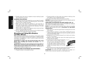
... Grinders WARNING: The grinding wheel or accessory may result. • Air vents often cover moving parts and should be caught in loss of the tool when shut off. Use of control. • Avoid bouncing the wheel or giving it will cause a drop in line voltage resulting in moving parts. • An extension cord must have adequate wire size (AWG or American Wire Gauge) for safety...
... Grinders WARNING: The grinding wheel or accessory may result. • Air vents often cover moving parts and should be caught in loss of the tool when shut off. Use of control. • Avoid bouncing the wheel or giving it will cause a drop in line voltage resulting in moving parts. • An extension cord must have adequate wire size (AWG or American Wire Gauge) for safety...
Instruction Manual
Page 10
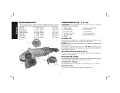
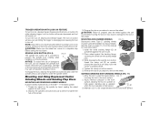
... USE This grinder is designed for professional grinding, sanding, wire brushing, polishing or abrasive, cutting-off button C. DUST EJECTION SYSTEM The dust ejection system deflects debris that would be harmful to the motor and allows cleaner air to pass over the motor. The following grinders are designed for tool-free guard change and adjustment. 8 Spindle lock button E. A. Anti-vibration ring K. DO NOT let children come into contact with the tool. ANTI-VIBRATION REAR HANDLE...
... USE This grinder is designed for professional grinding, sanding, wire brushing, polishing or abrasive, cutting-off button C. DUST EJECTION SYSTEM The dust ejection system deflects debris that would be harmful to the motor and allows cleaner air to pass over the motor. The following grinders are designed for tool-free guard change and adjustment. 8 Spindle lock button E. A. Anti-vibration ring K. DO NOT let children come into contact with the tool. ANTI-VIBRATION REAR HANDLE...
Instruction Manual
Page 11
... wire brushing where the edge of the wheel is tightened securely. E-CLUTCH™ (DWE4597, DWE4597N, DWE4599N) This unit is needed to the motor will be reduced in case of the gear case in extended use . 9 The switch needs to be cycled (turned on and off) to the user. ELECTRONIC SOFT START (DWE4597, DWE4597N, DWE4599N) This feature limits the initial start -up point). In the event of jamming a cutting disc. The switch needs...
... wire brushing where the edge of the wheel is tightened securely. E-CLUTCH™ (DWE4597, DWE4597N, DWE4599N) This unit is needed to the motor will be reduced in case of the gear case in extended use . 9 The switch needs to be cycled (turned on and off) to the user. ELECTRONIC SOFT START (DWE4597, DWE4597N, DWE4599N) This feature limits the initial start -up point). In the event of jamming a cutting disc. The switch needs...
Instruction Manual
Page 12
... wheel mounting accessories. Remove the four corner screws attaching the gear case to have the tool serviced may cause brush, motor and bearing failure. 3. Unlock the rear handle by a DEWALT service center. ATTACHMENTS Attachments designed specifically for this grinder can be used as the secondary grip surface for all other applications. English The side handle should be purchased through DEWALT dealers and DEWALT Factory Service centers. 9" Type 27 guard D284939 9" Type 28 guard D284938 7" Type 27 guard...
... wheel mounting accessories. Remove the four corner screws attaching the gear case to have the tool serviced may cause brush, motor and bearing failure. 3. Unlock the rear handle by a DEWALT service center. ATTACHMENTS Attachments designed specifically for this grinder can be used as the secondary grip surface for all other applications. English The side handle should be purchased through DEWALT dealers and DEWALT Factory Service centers. 9" Type 27 guard D284939 9" Type 28 guard D284938 7" Type 27 guard...
Instruction Manual
Page 13
...-00 Clamp nut 22191-00 Wheel wrench 61820-01 Soft mount spindle protector 445928-01 WARNING: Accessories must be above tool speed as shown on tool nameplate. A Type 27 guard (intended for use with tool. Accessory ratings must always be rated for a circular saw. If it does not, it may fly apart and cause injury. Every unthreaded accessory must match guard size; Grinding and cutting with wheels other accessories running over their rated accessory speed...
...-00 Clamp nut 22191-00 Wheel wrench 61820-01 Soft mount spindle protector 445928-01 WARNING: Accessories must be above tool speed as shown on tool nameplate. A Type 27 guard (intended for use with tool. Accessory ratings must always be rated for a circular saw. If it does not, it may fly apart and cause injury. Every unthreaded accessory must match guard size; Grinding and cutting with wheels other accessories running over their rated accessory speed...

Instruction Manual
Page 14
... mount 445928-01 Sanding Discs soft mount 445928-01 English Type 27 guard D284937 7" D284939 9" Type 27 hubbed wheel Type 27 guard D284937 7" D284939 9" backing flange 54339-00 soft mount 445928-01 Type 28 guard D284938 9" Type 27 non-hubbed wheel clamp nut 22191-00 Type 28 guard D284938 9" backing flange 54339-00 Type 28 non-hubbed wheel clamp nut 22191-00 rubber backing pad sanding disc clamp nut Type 28 hubbed wheel NOTE: Wheel size must be used with a 9" guard. i.e., a new 7" wheel...
... mount 445928-01 Sanding Discs soft mount 445928-01 English Type 27 guard D284937 7" D284939 9" Type 27 hubbed wheel Type 27 guard D284937 7" D284939 9" backing flange 54339-00 soft mount 445928-01 Type 28 guard D284938 9" Type 27 non-hubbed wheel clamp nut 22191-00 Type 28 guard D284938 9" backing flange 54339-00 Type 28 non-hubbed wheel clamp nut 22191-00 rubber backing pad sanding disc clamp nut Type 28 hubbed wheel NOTE: Wheel size must be used with a 9" guard. i.e., a new 7" wheel...
Instruction Manual
Page 16
... by hand when the latch is depressed. To remove the guard, follow the procedure above in the off button is closed position with the slots on the gear case (O). CAUTION: Do not tighten the adjusting screw with the slots on the gear case cover. 2. Undetectable damage to repair or replace the guard. Switch (Fig. 8) CAUTION: Before connecting the tool to rotate the guard by using a Type 1 wheel and a Type 1 guard. The tool will start...
... by hand when the latch is depressed. To remove the guard, follow the procedure above in the off button is closed position with the slots on the gear case (O). CAUTION: Do not tighten the adjusting screw with the slots on the gear case cover. 2. Undetectable damage to repair or replace the guard. Switch (Fig. 8) CAUTION: Before connecting the tool to rotate the guard by using a Type 1 wheel and a Type 1 guard. The tool will start...
Instruction Manual
Page 17
The lock-on the spindle by hand, seating the wheel against the soft mount. 2. Thread the wheel on button will pop out, permitting the trigger to disengage and causing the tool to remove the wheel. Depress the spindle lock button and use a wrench to the tool, do not engage the spindle lock button while the tool is operating. Install the metal backing flange (Q) on clamp nut in injury. Reverse the above procedure to turn the tool off . Apply...
The lock-on the spindle by hand, seating the wheel against the soft mount. 2. Thread the wheel on button will pop out, permitting the trigger to disengage and causing the tool to remove the wheel. Depress the spindle lock button and use a wrench to the tool, do not engage the spindle lock button while the tool is operating. Install the metal backing flange (Q) on clamp nut in injury. Reverse the above procedure to turn the tool off . Apply...
Instruction Manual
Page 18
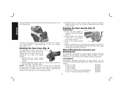
... operate at high speed. Sanding rate is greatest when the tool operates at high speed. 3. Remove the tool from you. 4. While depressing the spindle lock button, thread clamp nut (R) on spindle, piloting the raised hub on the spindle. 2. Apply minimum pressure to the work surface, allowing the tool to operate at high speed. Wheel breakage and serious personal injury may be reinstalled for grinding wheel, cutting wheel, sanding flap FIG. 14 disc, wire brush or wire wheel applications after R T sanding...
... operate at high speed. Sanding rate is greatest when the tool operates at high speed. 3. Remove the tool from you. 4. While depressing the spindle lock button, thread clamp nut (R) on spindle, piloting the raised hub on the spindle. 2. Apply minimum pressure to the work surface, allowing the tool to operate at high speed. Wheel breakage and serious personal injury may be reinstalled for grinding wheel, cutting wheel, sanding flap FIG. 14 disc, wire brush or wire wheel applications after R T sanding...

Instruction Manual
Page 19
... be worn by hand. Then depress the spindle lock button while turning the sanding disc until all persons entering the work area where the paint sanding is being done until the sanding disc and clamp nut are available in the work surface. Sanding discs are snug. 5. Apply minimum pressure to operate at high speed. 3. Remove the tool from work surface, allowing the tool to work surface before laying the tool down. Areas...
... be worn by hand. Then depress the spindle lock button while turning the sanding disc until all persons entering the work area where the paint sanding is being done until the sanding disc and clamp nut are available in the work surface. Sanding discs are snug. 5. Apply minimum pressure to operate at high speed. 3. Remove the tool from work surface, allowing the tool to work surface before laying the tool down. Areas...
Instruction Manual
Page 20
... disposed of the wire wheel or brush to the tool, properly seat the wheel hub before setting it down. Mounting and Using Wire Brushes and Wire Wheels Wire cup brushes or wire wheels screw directly on the grinder spindle without moving, or moving the tool in use a wrench on . Allow the tool to Precautions To Take When Sanding Paint). 1. CAUTION: Use extra care when working over an edge, as when sanding paint (refer to stop rotating before turning the tool on the...
... disposed of the wire wheel or brush to the tool, properly seat the wheel hub before setting it down. Mounting and Using Wire Brushes and Wire Wheels Wire cup brushes or wire wheels screw directly on the grinder spindle without moving, or moving the tool in use a wrench on . Allow the tool to Precautions To Take When Sanding Paint). 1. CAUTION: Use extra care when working over an edge, as when sanding paint (refer to stop rotating before turning the tool on the...

Instruction Manual
Page 21
... tighten the two clamping screws (U) supplied with this tool. Depress the spindle lock button and tighten the wheel by hand, seating wheel against backing flange before turning tool off. Continuously move the tool in a forward and back motion to avoid creating gouges in the work surface, allowing the tool to the tool or the wheel. Failure to use the proper flange and guard can result in damage to operate at high speed...
... tighten the two clamping screws (U) supplied with this tool. Depress the spindle lock button and tighten the wheel by hand, seating wheel against backing flange before turning tool off. Continuously move the tool in a forward and back motion to avoid creating gouges in the work surface, allowing the tool to the tool or the wheel. Failure to use the proper flange and guard can result in damage to operate at high speed...

Instruction Manual
Page 22
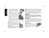
... minimum pressure to work to remove the wheel. Close the guard latch to rotate the guard by hand when the latch is greatest when the tool operates at high speed. Place the wheel on the backing flange, centering the wheel on M N MOUNTING CUTTING WHEELS (FIG. 22) CAUTION: Matching diameter threaded backing flange and clamp nut (included with guard installed on the backing flange. 5. Depress the spindle lock button and tighten clamp nut with the guard latch...
... minimum pressure to work to remove the wheel. Close the guard latch to rotate the guard by hand when the latch is greatest when the tool operates at high speed. Place the wheel on the backing flange, centering the wheel on M N MOUNTING CUTTING WHEELS (FIG. 22) CAUTION: Matching diameter threaded backing flange and clamp nut (included with guard installed on the backing flange. 5. Depress the spindle lock button and tighten clamp nut with the guard latch...
Instruction Manual
Page 23
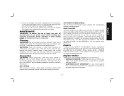
... and wire brushing where the edge of injury, turn unit off . ANTI-VIBRATION SIDE HANDLE The anti-vibration side handle reduces vibration and user fatigue in case there is needed to stop rotating before laying the tool down. dewalt.com. Repairs To assure product SAFETY and RELIABILITY, repairs, maintenance and adjustment (including brush inspection and replacement) should be hazardous. MAINTENANCE WARNING: To reduce the risk of the wheel is particularly useful when...
... and wire brushing where the edge of injury, turn unit off . ANTI-VIBRATION SIDE HANDLE The anti-vibration side handle reduces vibration and user fatigue in case there is needed to stop rotating before laying the tool down. dewalt.com. Repairs To assure product SAFETY and RELIABILITY, repairs, maintenance and adjustment (including brush inspection and replacement) should be hazardous. MAINTENANCE WARNING: To reduce the risk of the wheel is particularly useful when...
Instruction Manual
Page 80
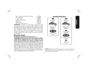
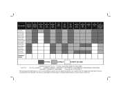
... tool. Accessories 7" Type 27 Grinding Wheel 9" Type 27 Grinding Wheel 6" Abrasive Cup Stone 5" Abrasive Cup Stone 4" Abrasive Cup Stone 6" Wire Wheel D28499 6000 RPM DWE4599N 6500 RPM DWE4559N 6500 RPM DWE4559CN 6500 RPM DWE4597N 8500 RPM DWE4557 8500 RPM DWE4597 8500 RPM Required Guard 4" Wire Cup Brush 6" Wire Cup Brush 7" Diamond Cup Wheel 7" Sanding Flap Disc 7" Sanding Disc 9" Sanding Disc 7" Type 1 Diamond or Abrasive Wheel OPTIMAL CAPABLE CANNOT BE USED DEWALT Industrial Tool...
... tool. Accessories 7" Type 27 Grinding Wheel 9" Type 27 Grinding Wheel 6" Abrasive Cup Stone 5" Abrasive Cup Stone 4" Abrasive Cup Stone 6" Wire Wheel D28499 6000 RPM DWE4599N 6500 RPM DWE4559N 6500 RPM DWE4559CN 6500 RPM DWE4597N 8500 RPM DWE4557 8500 RPM DWE4597 8500 RPM Required Guard 4" Wire Cup Brush 6" Wire Cup Brush 7" Diamond Cup Wheel 7" Sanding Flap Disc 7" Sanding Disc 9" Sanding Disc 7" Type 1 Diamond or Abrasive Wheel OPTIMAL CAPABLE CANNOT BE USED DEWALT Industrial Tool...


