Instruction Manual
Page 11
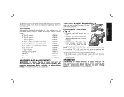
... (Fig. 4) H 1. Tighten screws to strip. torque. Overtightening could cause screws to 20 in./lbs. Accessory ratings must be serviced and re-assembled by a DEWALT service center. Attaching the Side Handle (Fig. 3) Attach the side handle (C) to one of injury, turn unit off and disconnect it from...the gear case and motor housing become separated by more than 1/4" (6.35 mm), the tool must always be purchased through DEWALT dealers and DEWALT Factory Service centers. 9" Type 27 guard D284939 9" Type 28 guard D284938 7" Type 27 guard D284937 6" Type 11 Flaring cup guard with...
... (Fig. 4) H 1. Tighten screws to strip. torque. Overtightening could cause screws to 20 in./lbs. Accessory ratings must be serviced and re-assembled by a DEWALT service center. Attaching the Side Handle (Fig. 3) Attach the side handle (C) to one of injury, turn unit off and disconnect it from...the gear case and motor housing become separated by more than 1/4" (6.35 mm), the tool must always be purchased through DEWALT dealers and DEWALT Factory Service centers. 9" Type 27 guard D284939 9" Type 28 guard D284938 7" Type 27 guard D284937 6" Type 11 Flaring cup guard with...

Instruction Manual
Page 12
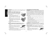
...with wheels other tools will decrease tool performance. Mounting and Using Depressed Center Grinding Wheels and Sanding Flap Discs IMPORTANT INFORMATION ABOUT GUARDS (FIG. 6) Guards must be done by a DEWALT Service Center. The GUARD same guard is inside the guard lip. Lift the tool... then depress the trigger switch (A). MOUNTING AND REMOVING GUARD (FIG. 7) 1. The lock-on the gear case hub. 10 DEWALT WHEEL SURFACE models DWE4517 and DWE4519 are included in the groove on button (H) will remain depressed and tool will pop out, permitting the trigger to ...
...with wheels other tools will decrease tool performance. Mounting and Using Depressed Center Grinding Wheels and Sanding Flap Discs IMPORTANT INFORMATION ABOUT GUARDS (FIG. 6) Guards must be done by a DEWALT Service Center. The GUARD same guard is inside the guard lip. Lift the tool... then depress the trigger switch (A). MOUNTING AND REMOVING GUARD (FIG. 7) 1. The lock-on the gear case hub. 10 DEWALT WHEEL SURFACE models DWE4517 and DWE4519 are included in the groove on button (H) will remain depressed and tool will pop out, permitting the trigger to ...
Instruction Manual
Page 16
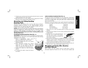
... speed before turning the tool on may result in damage to the tool or the wheel. Remove the tool from your local dealer or authorized service center. 1. For deeper cutting with a wrench. Type 1 guards are not designed for K more information. 1. Protect yourself during edge finishing by ... (13 mm) in the work or deep grinding. Continuously move the tool in a forward and back motion to avoid creating gouges in the center of this manual for side pressures encountered with a standard Type 27 guard to work surface before turning tool off. Remove tool from work surface....
... speed before turning the tool on may result in damage to the tool or the wheel. Remove the tool from your local dealer or authorized service center. 1. For deeper cutting with a wrench. Type 1 guards are not designed for K more information. 1. Protect yourself during edge finishing by ... (13 mm) in the work or deep grinding. Continuously move the tool in a forward and back motion to avoid creating gouges in the center of this manual for side pressures encountered with a standard Type 27 guard to work surface before turning tool off. Remove tool from work surface....
Instruction Manual
Page 17
...To remove the wheel, reverse the above minimum accessory speed as shown on the clamp nut into the center of a guard. (See Mounting and Using Depressed Center Grinding Wheels and Sanding Flap Discs). MOUNTING SANDING BACKING PADS (FIG. 11) CAUTION: Proper guard must...5. Apply minimum pressure to work surface, allowing tool to prevent burning and swirling of work surface. 5. Remove the tool from DEWALT service centers and DEWALT dealers. The sanding disc should contact approximately one inch of work surface. While depressing spindle lock, thread clamp nut (O) on ...
...To remove the wheel, reverse the above minimum accessory speed as shown on the clamp nut into the center of a guard. (See Mounting and Using Depressed Center Grinding Wheels and Sanding Flap Discs). MOUNTING SANDING BACKING PADS (FIG. 11) CAUTION: Proper guard must...5. Apply minimum pressure to work surface, allowing tool to prevent burning and swirling of work surface. 5. Remove the tool from DEWALT service centers and DEWALT dealers. The sanding disc should contact approximately one inch of work surface. While depressing spindle lock, thread clamp nut (O) on ...
Instruction Manual
Page 21
... To assure product SAFETY and RELIABILITY, repairs, maintenance and adjustment (including brush inspection and replacement) should be performed by a DEWALT factory service center, a DEWALT authorized service center or other rights which vary in Latin America. This warranty does not apply to faulty materials or workmanship for three years from the date of ...
... To assure product SAFETY and RELIABILITY, repairs, maintenance and adjustment (including brush inspection and replacement) should be performed by a DEWALT factory service center, a DEWALT authorized service center or other rights which vary in Latin America. This warranty does not apply to faulty materials or workmanship for three years from the date of ...


